Reluctance rotor, motor and compressor

A rotor and reluctance technology, applied in the field of compressors, can solve the problems of high cost, unacceptable market, and low motor efficiency.

Inactive Publication Date: 2021-03-12
ZHUHAI GREE REFRIGERATION TECH CENT OF ENERGY SAVING & ENVIRONMENTAL PROTECTION
View PDF3 Cites 0 Cited by
  • Summary
  • Abstract
  • Description
  • Claims
  • Application Information

AI Technical Summary

Problems solved by technology

[0002] At present, there are permanent magnet synchronous reluctance rotors. The torque of reluctance motors is basically composed of two parts: electromagnetic torque and reluctance torque. Too low electromagnetic torque will make the efficiency of the motor low, and the magnetic energy of rare earth mag

Method used


Image

  • Reluctance rotor, motor and compressor
  • Reluctance rotor, motor and compressor
  • Reluctance rotor, motor and compressor

Examples


Embodiment Construction

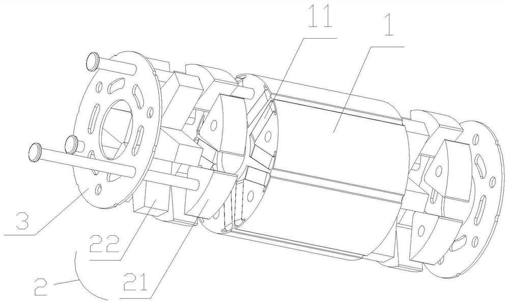
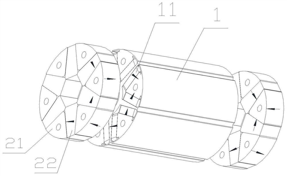
[0025] see in conjunction Figure 1 to Figure 5 As shown, according to an embodiment of the present application, a reluctance rotor includes:

[0026] The rotor core 1 includes a magnetic steel slot;

[0027] The first magnetic steel part 11 is arranged in the magnetic steel groove;

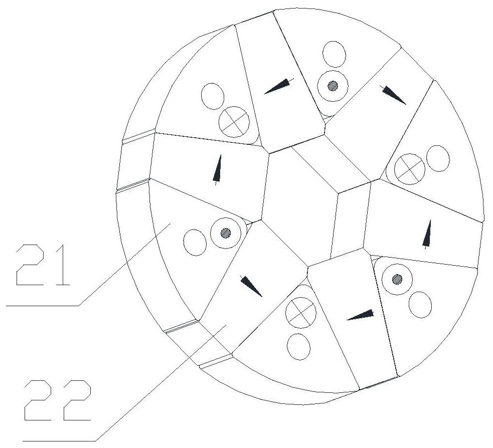
[0028] The second magnetic steel part 2 is arranged on the end surface of the rotor core 1 .

[0029] Since the reluctance motors are all axially symmetrical structures, the first magnetic steel part 11 is arranged in the magnetic steel slot provided in the rotor core 1, and the leakage reactance at the end is relatively large, and the utilization rate of the magnetic steel is low; The second magnetic steel part 2 is arranged on the end surface of 1, which can form a three-dimensional magnetic gathering structure, reduce leakage reactance at the end, increase the utilization rate of the magnetic steel, and improve the electromagnetic torque ratio.

[0030] In some embodiments, the second magne...


PUM


Abstract

The invention provides a reluctance rotor, a motor and a compressor. The reluctance rotor comprises a rotor iron core which comprises a magnetic steel groove; a first magnetic steel piece arranged inthe magnetic steel groove; and a second magnetic steel piece arranged on the end surface of the rotor core. The second magnetic steel piece is additionally arranged on the outer side of the magnetic steel arranged in a traditional magnetic steel groove, end leakage reactance can be reduced, the utilization rate of the magnetic steel is increased, and the electromagnetic torque proportion is increased.

Description

technical field [0001] The application belongs to the technical field of compressors, and in particular relates to a reluctance rotor, a motor and a compressor. Background technique [0002] At present, there are permanent magnet synchronous reluctance rotors. The torque of reluctance motors is basically composed of two parts: electromagnetic torque and reluctance torque. Too low electromagnetic torque will make the efficiency of the motor low, and the magnetic energy of rare earth magnets will be far away. It is higher than ferrite magnets, but the cost is much higher than that of ferrite magnets. The market cannot accept it. It is necessary to find a new structure to improve the efficiency of the motor and improve the cost performance of the motor without greatly increasing the cost. Contents of the invention [0003] Therefore, the technical problem to be solved in the present application is to provide a reluctance rotor, a motor and a compressor, which can reduce leaka...

Claims


Application Information

Patent Timeline
IPC IPC(8): H02K1/27
CPCH02K1/2766
Inventor 龚海涛
Owner ZHUHAI GREE REFRIGERATION TECH CENT OF ENERGY SAVING & ENVIRONMENTAL PROTECTION
Why Eureka
Try Eureka