Camera module and working method thereof

A camera module and lens module technology, applied in image communication, TV, color TV components and other directions, can solve the problem of difficult movement of the lens module, etc.

Pending Publication Date: 2021-03-12
GALAXYCORE SHANGHAI
View PDF0 Cites 3 Cited by
  • Summary
  • Abstract
  • Description
  • Claims
  • Application Information

AI Technical Summary

Problems solved by technology

[0006] However, in the traditional technology, the camera module that can realize the closed-loop c

Method used


Image

  • Camera module and working method thereof
  • Camera module and working method thereof
  • Camera module and working method thereof

Examples


Embodiment Construction

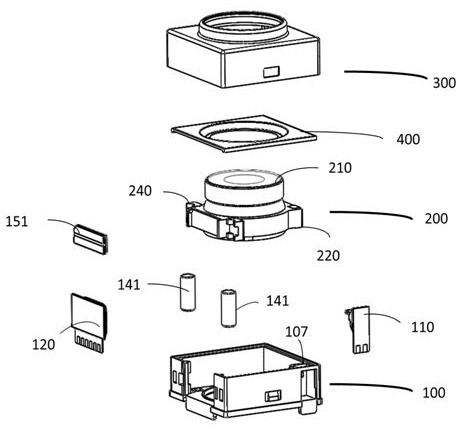
[0055] In order to solve the above-mentioned problems in the prior art, the present invention provides a camera module, in which the moving stroke of the lens module can realize a large stroke.

[0056] In the following detailed description of the preferred embodiment, reference is made to the accompanying drawings which form a part hereof. The accompanying drawings show, by way of example, specific embodiments in which the invention can be practiced. The illustrated embodiments are not intended to be exhaustive of all embodiments in accordance with the invention. It is to be understood that other embodiments may be utilized and structural or logical changes may be made without departing from the scope of the present invention. Accordingly, the following detailed description is not limiting, and the scope of the invention is defined by the appended claims.

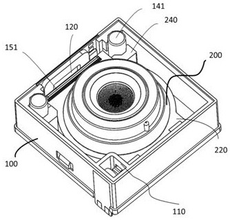
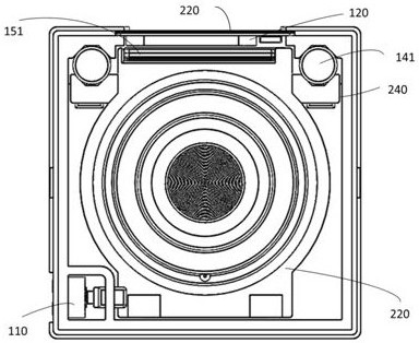
[0057] Such as figure 1 As shown, the embodiment of the present invention provides a camera module, including: a mov...


PUM

PropertyMeasurementUnit
Opening angleaaaaaaaaaa

Abstract

The invention provides a camera module and a working method thereof. The camera module comprises a moving unit, a fixing unit and at least one locking structure; the moving unit comprises a lens module and is suitable for driving the lens module to move in the optical axis direction; and the fixing unit is suitable for bearing the moving unit, and the locking structure is arranged in the fixing unit and is suitable for locking or unlocking the moving unit. According to the camera module and the working method thereof provided by the invention, the lens module can have a relatively large movingstroke.

Description

technical field [0001] The invention relates to a camera module and its working method. Background technique [0002] With the rapid development of the smartphone industry, people's requirements for the imaging effect of mobile phone cameras are also gradually increasing. Compared with traditional camera systems, the Cell phone Camera Module (CCM) is Due to the advantages of low cost and high image quality, it is widely used in various new generation portable camera equipment. [0003] At present, the structure of the camera module includes a lens unit, a voice coil motor (Voice Coil Motor, VCM), an infrared cut filter, an image sensor, a flexible printed circuit board (Flexible Printed Circuit board, FPC) or a printed circuit board (Printed Circuit Board). Circuit Board, PCB), and the connector connected to the mobile phone motherboard. [0004] Wherein, the voice coil motor is used to realize the auto-focus function of the lens unit, and the voice coil motor usually incl...

Claims


Application Information

Patent Timeline
IPC IPC(8): H04N5/225H04N5/232
CPCH04N23/50H04N23/57H04N23/55H04N23/51H04N23/54H04N23/67
Inventor 杜智勇许勇
Owner GALAXYCORE SHANGHAI
Why Eureka
Try Eureka