
Mechanism for disassembling disc parts of aero-engine

A technology for aero-engine and disk parts, which is applied in the field of disk parts decomposition, can solve the complexity of the assembly and decomposition process, and achieve the effect of simple operation process, meeting the needs of production and use, and improving production efficiency

Inactive Publication Date: 2021-03-16
SHENYANG LIMING AERO-ENGINE GROUP CORPORATION
View PDF5 Cites 2 Cited by
  • Summary
  • Abstract
  • Description
  • Claims
  • Application Information

AI Technical Summary

Problems solved by technology

[0002] Interference fit is mostly used for the connection of various disk parts in aero-engines, and there is a certain degree of complexity in the process of assembly and disassembly
However, in the process of manufacturing and repairing, it often needs to be disassembled many times to adjust the engine to the optimal state.

Method used


Image

  • Mechanism for disassembling disc parts of aero-engine
  • Mechanism for disassembling disc parts of aero-engine
  • Mechanism for disassembling disc parts of aero-engine

Examples


Embodiment Construction

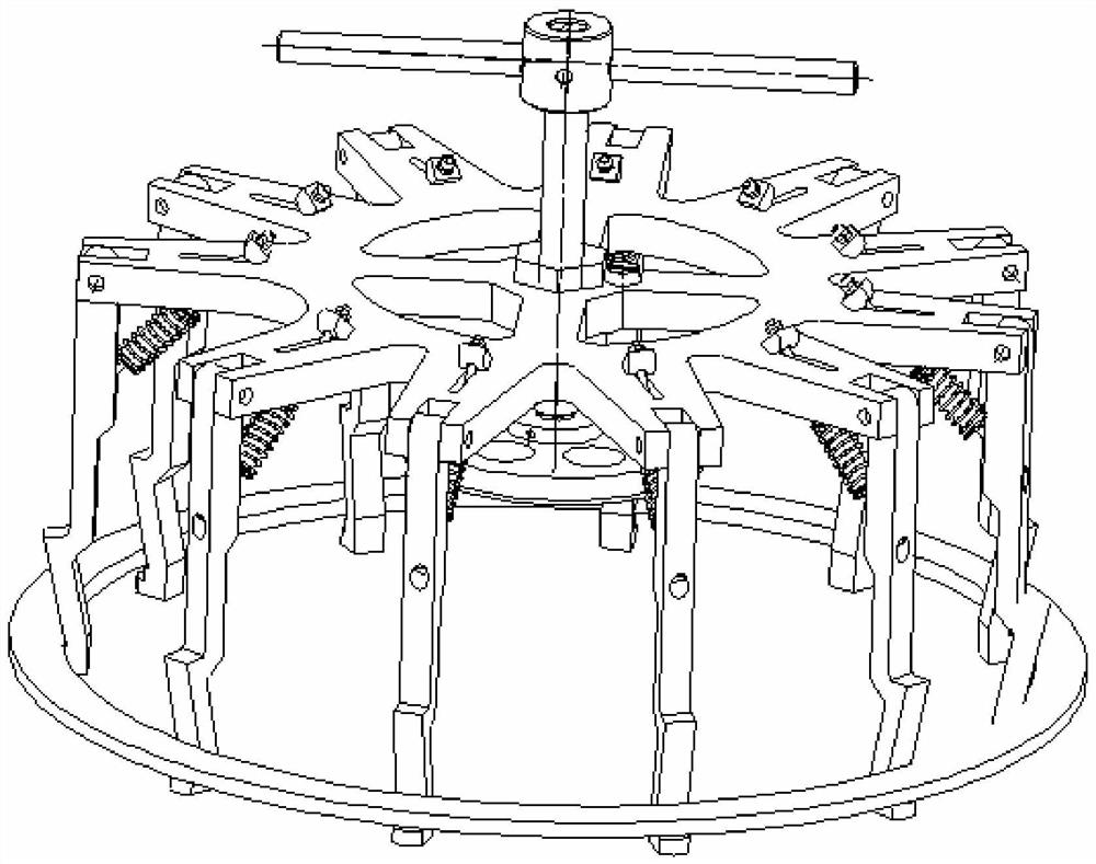
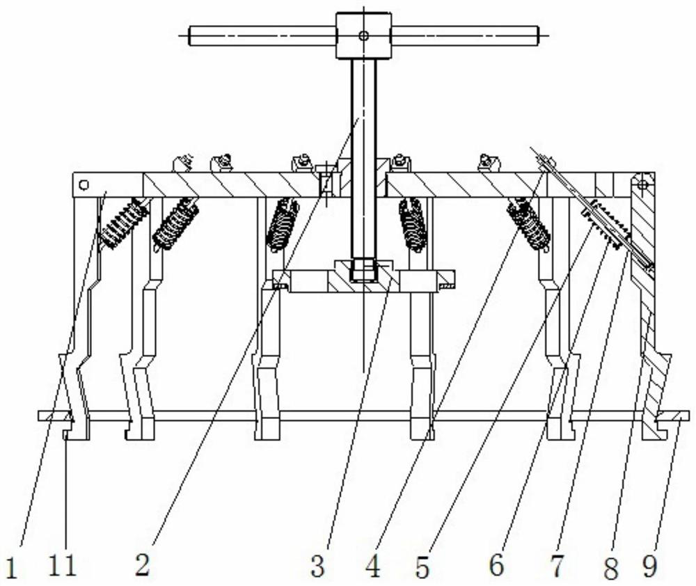
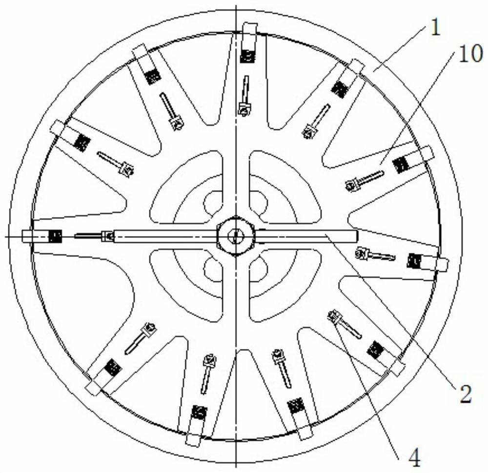
[0028] Such as Figure 1-3 A mechanism for disassembling disc parts of an aero-engine is shown, which is characterized in that it includes a tray 1, a tightening bolt 2, a tightening disc 3, an R-shaped nut 4, a spring 5, a spring mandrel 6, a pull rod 7, a clamp Claw 8 and limit ring 9;

[0029] The tray 1 is disc-shaped, with eleven mounting teeth 10 distributed around the circumference; and the mounting teeth are provided with bar-shaped grooves;

[0030] One end of the claw 8 is connected to the mounting tooth 10 of the tray;

[0031] The other end of the claw 8 is provided with a step-shaped clamping platform 11 that cooperates with the limit ring 9;

[0032] One end of the pull rod 7 is connected to the wall of the claw 8, and the other end is connected to the bar groove of the installation tooth 10, and the pull rod 7 is provided with a spring mandrel 6, the spring 5 is sleeved on the spring mandrel 6, and the pull rod 7 Clamped on the bar groove through the R-type n...


PUM


Abstract

The invention discloses a mechanism for disassembling disc parts of an aero-engine. A plurality of mounting teeth are distributed on the circumference of a tray; one end of a clamping jaw is connectedto the mounting teeth of the tray; a step-shaped clamping table matched with a limiting ring is arranged at the other end of the clamping jaw; one end of a pull rod is connected to the wall of the clamping jaw, the other end of the pull rod is connected into a strip-shaped groove of the mounting teeth, a spring mandrel is arranged on the pull rod, a spring is sleeved on the spring mandrel, and the pull rod is clamped on the strip-shaped groove through an R-shaped nut; a puller bolt penetrates through the tray, the middle position of the puller bolt is connected with a threaded bushing arranged on the tray, the puller bolt abuts against a threaded blind hole formed in a puller disc, downward force of the threaded bushing of the tray is received through the puller bolt, and the force is applied to the puller disc; and the limiting ring is arranged at the other end of the claw. The clamping jaw capable of rotating and swinging is adopted, the requirement that the clamping jaw can extendinto the rear end of a disc part to pull the disc part to be disassembled is met, and the position of the mechanism clamping jaw can be flexibly adjusted.

Description

technical field [0001] The invention relates to the technical field of disc parts disassembly, in particular to a mechanism for disassembling aero-engine disc parts. Background technique [0002] Interference fit is mostly used for the connection of various disk parts in aero-engines, and there is a certain complexity in the process of assembly and disassembly. However, in the process of manufacturing and repairing, multiple disassembly is often required to adjust the engine to the optimal state. Contents of the invention [0003] In order to solve the above-mentioned technical problems, a kind of mechanism specific technical scheme for dismantling aero-engine disk parts is proposed as follows: [0004] A mechanism for disassembling disc parts of an aero-engine, comprising a tray, jacking bolts, jacking discs, R-shaped nuts, springs, spring mandrels, pull rods, claws and limit rings; [0005] The tray is disc-shaped, with a plurality of installation teeth distributed aro...

Claims


Application Information

Patent Timeline
IPC IPC(8): B25B27/02
CPCB25B27/023
Inventor 陈宏海彭会文王艺格庄涛李硕
Owner SHENYANG LIMING AERO-ENGINE GROUP CORPORATION
Learn More