
Special stud welding equipment dedicated to coated plate

A technology of stud welding and coated plates, applied in welding equipment, arc welding equipment, metal processing equipment, etc., can solve problems such as insignificant effect, poor effect, and secondary damage to the workpiece

Active Publication Date: 2021-05-04
洛阳市锐创电气设备有限公司
View PDF6 Cites 0 Cited by
  • Summary
  • Abstract
  • Description
  • Claims
  • Application Information

AI Technical Summary

Problems solved by technology

[0003] During the processing of nails, the surface of the coated plate is different from the internal material, and there are differences in conductivity and melting point. It is more likely to cause spatter, welding beads, black discs and even welding nails during welding. Due to the coating coating, it is difficult to weld firmly. , and even ordinary plates, due to different factors such as surface oxidation or processing environment, welding beads, black discs, etc. will appear during welding. Two methods are often used in the existing market: 1. Manual pretreatment The method of using a grinder and other tools to polish the surface of the coated sheet will not only cause secondary damage to the workpiece, but also increase the labor intensity of the workers and the effect is not good
2. Increase the welding time for a longer time so that the coating on the surface of the plate is completely melted and the studs are fused together. This method can play a role in firm welding under certain conditions, but it has no effect on solving welding beads, black plates, etc. Obviously, in addition, long-term welding heating can also increase the probability of thermal deformation, which is not suitable for stud welding operations between thin plates and mirror stainless steel plates

Method used


Image

  • Special stud welding equipment dedicated to coated plate
  • Special stud welding equipment dedicated to coated plate
  • Special stud welding equipment dedicated to coated plate

Examples


specific Embodiment 1

[0024] Specific embodiment 1: The technical solution of the present invention will be clearly and completely described below in conjunction with the embodiments. Obviously, the described embodiments are part of the embodiments of the present invention, but not all of them. Based on the embodiments of the present invention, all other embodiments obtained by persons of ordinary skill in the art without making creative efforts belong to the protection scope of the present invention. It should be noted that in the present invention, unless otherwise specified, all the implementation modes and preferred implementation methods mentioned herein can be combined with each other to form a new technical solution. In the present invention, if there is no special description, all the technical features and preferred features mentioned herein can be combined with each other to form a new technical solution. In the present invention, unless otherwise specified, the various components involve...


PUM


Abstract

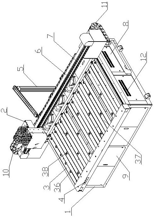
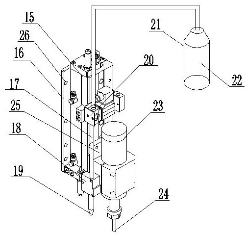
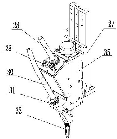
The invention relates to the field of stud welding equipment, in particular to special stud welding equipment dedicated to a coated plate. The special stud welding equipment comprises a rack, a machine head mounting frame, a working platform, a control button box, a welding stud conveying pipe suspender, a vibration disc, a truss, a welding machine resistance box, a welding machine distribution box, an X-axis drag chain, a Y-axis drag chain, a welding machine, a welding gun assembly and pretreatment equipment; and the working platform is mounted on the rack and is fixedly connected with the rack. According to the special stud welding equipment, the pretreatment equipment on the machine head mounting frame can be used for firstly carrying out coating elimination operation on a coating plate on the working platform, and anti-splashing liquid is sprayed on the coating plate on the working platform through a liquid spraying nozzle; the coating eliminating operation and the spraying splash-proof operation can remarkably reduce sparks, splashing and black plates generated when the stud welding is carried out on the surface of the coating plate, the welding firmness degree of the coating plate is improved, and the rate of finished products is increased.

Description

technical field [0001] The invention relates to the field of stud welding equipment, in particular to special stud welding equipment for coated plates. Background technique [0002] Stud arc welding (SW) is an arc welding method that uses an arc between a metal stud (which can be similar to a part) and a plate-shaped workpiece to achieve welding. This method uses no filler metal, may be used with or without shielding gas or flux, and generally applies pressure to sufficiently melt the joining surfaces. This method was invented in the 1930s. The stud welding technology has been gradually automated from the complete use of labor to the current stage, and new equipment and new technologies are also emerging. Although the ordinary stud welding equipment using the industrial control system increases the accuracy and saves the cost of manpower, it still exists. The following questions. [0003] During the processing of nails, the surface of the coated plate is different from th...

Claims


Application Information

Patent Timeline
IPC IPC(8): B23K9/20B23K9/235B23K9/32
CPCB23K9/20B23K9/235B23K9/32
Inventor 付强马玉林樊英国
Owner 洛阳市锐创电气设备有限公司
Learn More