
Welding head of stainless steel cold rolling production line welding machine

A production line, stainless steel technology, applied in the direction of welding equipment, resistance welding equipment, metal processing equipment, etc., can solve the problems of affecting the production rhythm of the front and rear processes, rising production costs, high spare parts costs, etc., to achieve welding stability and welding quality Improvement and reduction Cost of spare parts, effect of extending service life

Pending Publication Date: 2022-05-06
本钢不锈钢冷轧丹东有限责任公司
View PDF0 Cites 0 Cited by
  • Summary
  • Abstract
  • Description
  • Claims
  • Application Information

AI Technical Summary

Problems solved by technology

[0002] The stainless steel cold rolling plant has many production processes and needs to go through harsh working conditions such as continuous annealing and pickling. The production line needs to operate continuously. If a shutdown occurs, it will seriously affect the production rhythm of the front and rear processes and cause an increase in production costs. Therefore, it is necessary to The strip steel is welded to meet the above working conditions. In order to improve the quality of the weld seam and prevent the strip from breaking and cutting the surface of the work roll on the production line, most of the welding machines in the stainless steel cold rolling plant use imported narrow lap resistance welding machines. The welding head of the welding machine is the core spare part that directly determines the welding quality, so foreign manufacturers impose a strict technical blockade on it. If the welding head spare parts are needed, they can only be imported from abroad, resulting in high spare parts costs and long procurement cycles.

Method used


Image

  • Welding head of stainless steel cold rolling production line welding machine
  • Welding head of stainless steel cold rolling production line welding machine
  • Welding head of stainless steel cold rolling production line welding machine

Examples


Embodiment Construction

[0017] The following will clearly and completely describe the technical solutions in the embodiments of the present invention with reference to the accompanying drawings in the embodiments of the present invention. Obviously, the described embodiments are only some, not all, embodiments of the present invention. Based on the embodiments of the present invention, all other embodiments obtained by persons of ordinary skill in the art without making creative efforts belong to the protection scope of the present invention.

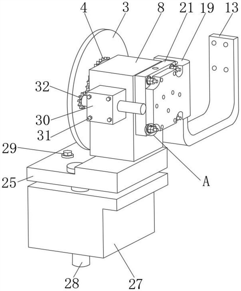
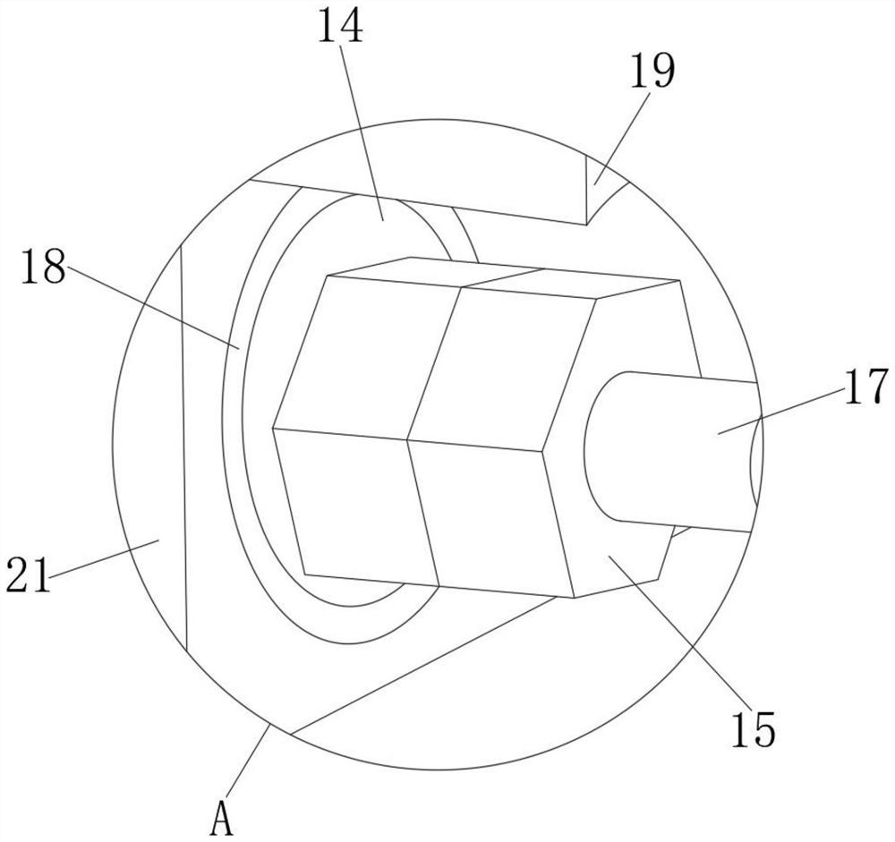
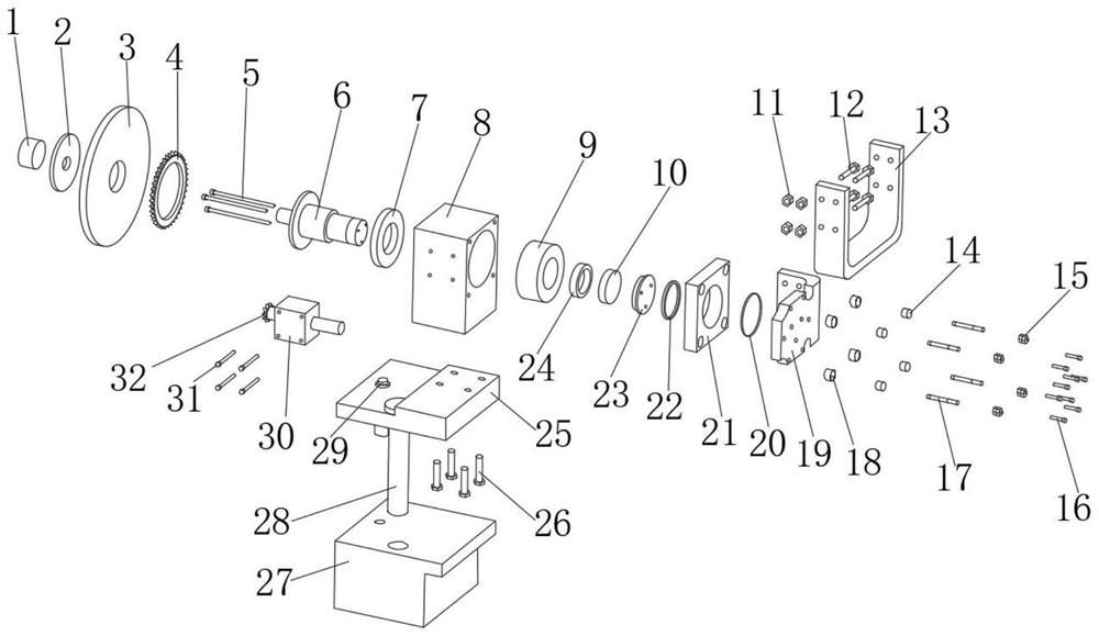
[0018] see Figure 1-3 , an embodiment provided by the present invention: a welding head of a stainless steel cold rolling production line, including a first nut 1, a pressure plate 2, a welding wheel 3, a first gear 4, a first bolt 5, a main shaft 6, and a first bearing 7. Main body frame 8, second bearing 9, concave copper ball 10, second nut 11, second bolt 12, conductive copper plate 13, disc spring 14, third nut 15, third bolt 16, fourth bolt 17, fixed R...


PUM


Abstract

The invention discloses a welding head of a stainless steel cold rolling production line welding machine. Comprising a first nut, a pressing plate, a welding wheel, a first gear, a first bolt, a main shaft, a first bearing, a main body frame, a second bearing, a concave copper ball, a second nut, a second bolt, a conductive copper plate, a disc spring, a third nut, a third bolt, a fourth bolt, a fixing ring, a cooling copper plate, a first sealing ring, a flange, a second sealing ring, a convex copper ball, a fourth nut, an upper base, a fifth bolt and a lower base. According to the stainless steel cold rolling welding head, the independently designed welding head can meet the production and use requirements of stainless steel cold rolling, use of an imported welding head is replaced, and the cost of spare parts is greatly reduced; by means of the independently-designed welding head structure, the welding efficiency and precision of the welding machine can be improved, and the welding stability and the welding quality are both improved; the contact stress is controlled through the disc spring, and the service life of the welding head is effectively prolonged.

Description

technical field [0001] The invention relates to the technical field of welder horns, in particular to a welder horn for a stainless steel cold rolling production line. Background technique [0002] The stainless steel cold rolling plant has many production processes and needs to go through harsh working conditions such as continuous annealing and pickling. The production line needs to operate continuously. If a shutdown occurs, it will seriously affect the production rhythm of the front and rear processes and cause an increase in production costs. Therefore, it is necessary to The strip steel is welded to meet the above working conditions. In order to improve the quality of the weld seam and prevent the strip from breaking and cutting the surface of the work roll on the production line, most of the welding machines in the stainless steel cold rolling plant use imported narrow lap resistance welding machines. The welding head of the welding machine is the core spare part that...

Claims


Application Information

Patent Timeline
Patent Type & Authority Applications(China)
IPC IPC(8): B23K11/36B23K11/00
CPCB23K11/36B23K11/00
Inventor 王德顺孙龙臻王元强韩松鹏
Owner 本钢不锈钢冷轧丹东有限责任公司
Learn More