Plate burr removing device for furniture processing
A technology for removing burrs and plates, which is applied in the field of plate burrs removal devices for furniture processing, and can solve problems such as poor deburring effect, easy hand stabbing, and cumbersome operation
- Summary
- Abstract
- Description
- Claims
- Application Information
AI Technical Summary
Problems solved by technology
Method used
Image
Examples
Embodiment 1
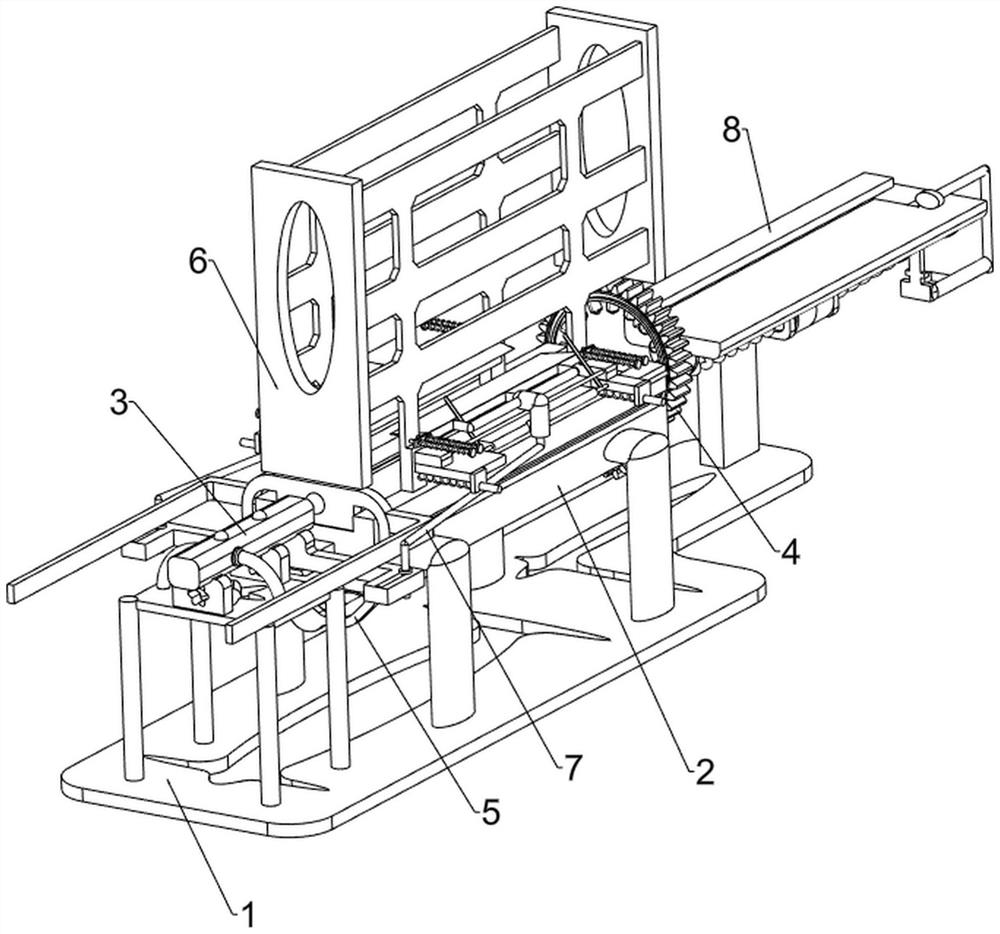
[0064] A device for removing burrs from boards for furniture processing, such as figure 1 As shown, it includes an underframe 1, a workbench 2, a push mechanism 3 and a deburring mechanism 4, an intermediate workbench 2 on the underframe 1, and a push mechanism 3 on the upper front side of the underframe 1, and the push mechanism 3 and the workbench 2 Sliding connection, the rear side of the pushing mechanism 3 is provided with a deburring mechanism 4.
[0065] When people need to process and deburr a furniture board, this deburring device can be used. First, people put the board on the workbench 2, and then start the pushing mechanism 3, which pushes the board to the deburring mechanism 4 At the position, open the deburring mechanism 4, and the deburring mechanism 4 sprays fire to deburr the plate, and then closes the pushing mechanism 3 and the deburring mechanism 4 after the burrs are removed.
Embodiment 2
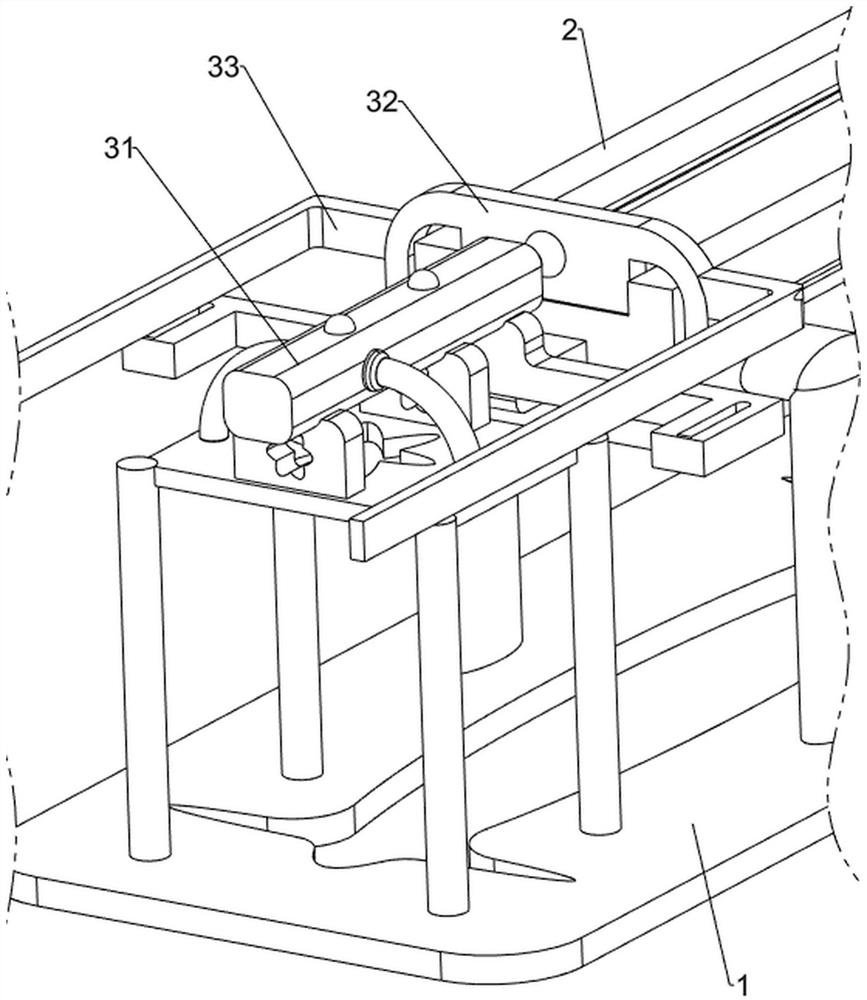
[0067] On the basis of Example 1, such as figure 2 and image 3As shown, the push mechanism 3 includes a cylinder 31, a push plate 32 and an outer expansion plate 33, and the front side of the bottom frame 1 is equipped with a cylinder 31, and the telescopic rod of the cylinder 31 is provided with a push plate 32, and the push plate 32 slides with the workbench 2 type connection, the left and right sides of the middle part of the push plate 32 are provided with external expansion plates 33.
[0068] After people put the board on the workbench 2, they open the cylinder 31, the extension of the cylinder 31 drives the push plate 32 to move backward, and the push board 32 pushes the board backward to the deburring mechanism 4 to realize the effect of pushing the board, and expand the board 33 moves together with push plate 32, after cylinder 31 shortens and drives push plate 32 to move forward and reset, close cylinder 31.
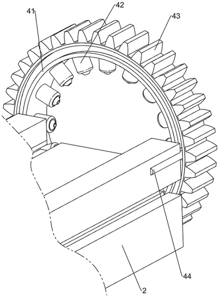
[0069] The deburring mechanism 4 includes a grooved r...
Embodiment 3
[0072] On the basis of Example 2, such as Figure 4-10 Shown, also comprise rotating mechanism 5, and rotating mechanism 5 comprises fixed frame 51, first threaded rod 52, second fixed claw 53 and pinion 54, and push plate 32 bottoms are provided with fixed frame 51, and fixed frame 51 is provided with There is a first threaded rod 52, a second fixed claw 53 is provided on the rear side of the bottom of the workbench 2, the second fixed claw 53 is slidingly connected with the first threaded rod 52, and a pinion 54 is rotatably arranged on the second fixed claw 53, The pinion 54 is threadedly connected with the first threaded rod 52 , and the pinion 54 meshes with the external rack 43 .
[0073] Push plate 32 moves back and forth to drive fixed frame 51 to move back and forth, thereby drives first threaded rod 52 to move back and forth, and then drives pinion 54 to rotate continuously, because pinion 54 meshes with external rack 43, external rack 43 is rotated continuously, rea...
PUM
 Abstract
Description
Claims
Application Information
 - R&D
- Intellectual Property
- Life Sciences
- Materials
- Tech Scout
- Unparalleled Data Quality
- Higher Quality Content
- 60% Fewer Hallucinations
Browse by: Latest US Patents, China's latest patents, Technical Efficacy Thesaurus, Application Domain, Technology Topic, Popular Technical Reports.
© 2025 PatSnap. All rights reserved.Legal|Privacy policy|Modern Slavery Act Transparency Statement|Sitemap|About US| Contact US: help@patsnap.com


