
Raw material mixing device for concrete production

A mixing device and concrete technology, which is applied to clay preparation devices, cement mixing devices, chemical instruments and methods, etc., can solve the problems of single rotating shaft, uneven mixing, etc., and achieve the effect of improving the mixing effect and improving the mixing effect

Inactive Publication Date: 2021-03-16
徐乔枝
View PDF0 Cites 0 Cited by
  • Summary
  • Abstract
  • Description
  • Claims
  • Application Information

AI Technical Summary

Problems solved by technology

[0003] During the production process of concrete, liquid raw materials need to be stirred and mixed, and the existing mixing device usually uses a single rotating shaft for mixing, which leads to the phenomenon of mixing stratification and uneven mixing. Therefore, a concrete production method is proposed. Use raw material mixing device to solve this technical problem

Method used


Image

  • Raw material mixing device for concrete production
  • Raw material mixing device for concrete production
  • Raw material mixing device for concrete production

Examples


Embodiment 1

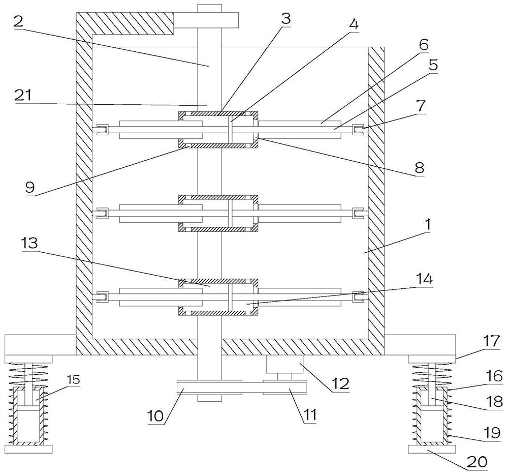
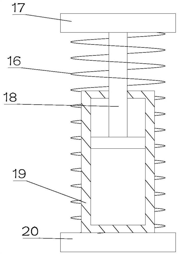
[0025] see Figure 1~3 , in Embodiment 1 of the present invention, it is a structural diagram of a raw material mixing device for concrete production provided by the embodiment of the present invention, including: a device main body 1, which is provided with a mixing chamber for raw material mixing;

[0026] Stirring component 2 is eccentrically arranged inside the device main body 1;

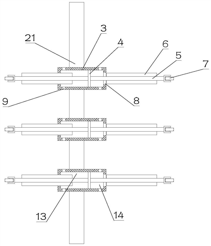
[0027] Wherein, the stirring assembly 2 includes a stirring shaft 21 which is eccentrically rotated inside the device main body 1, and a plurality of cylinders 3 are arranged in an array on the stirring shaft 21, and a plurality of cylinders 3 are provided with reciprocating sliding pistons. 4. The connecting rod 5 is set through the cylinder body 3 and the piston 4, and the piston 4 is fixedly arranged at the middle position of the connecting rod 5, the piston 4 is fixedly installed on the connecting rod 5, and the two ends of the connecting rod 5 are respectively slid and pasted on the On th...

Embodiment 2

[0031] see Figure 1~3 , in Embodiment 2 of the present invention, both ends of the connecting rod 5 are provided with stirring blades 6 , and the stirring blades 6 are arranged on the upper and lower sides of the connecting rod 5 . Thus, the raw materials can be well stirred and mixed.

[0032] The piston 4 divides the interior of the cylinder 3 into a first cavity 13 and a second cavity 14, and the end of the first cavity 13 and the second cavity 14 away from the piston 4 is provided with a through hole 8, and the through hole 8 is set. 8 to facilitate the passage of the connecting rod 5; the ends of the first cavity 13 and the second cavity 14 are respectively provided with communication holes 9, which facilitate the entry of raw materials or the removal of raw materials.

[0033] Specifically, when the connecting rod 5 rotates with the stirring shaft 21, due to the eccentric arrangement of the stirring assembly 2, the piston 4 slides back and forth inside the barrel 3, th...


PUM


Abstract

The invention is suitable for the technical field of concrete production, and provides a raw material mixing device for concrete production. The raw material mixing device comprises a device main bodywhich is internally provided with a stirring cavity for mixing raw materials, a stirring assembly which is eccentrically arranged in the device main body and a driving assembly, wherein the stirringassembly comprises a stirring assembly body eccentrically arranged in the device main body in a self-rotating manner, a plurality of cylinders are arranged on the stirring assembly body in an array manner, pistons are arranged in the cylinders in a reciprocating sliding manner, connecting rods penetrate through the cylinders and the pistons, and the pistons are fixedly arranged in the middles of the connecting rods; the pistons are fixedly installed on the connecting rods, and the two ends of the connecting rods are attached to the inner wall of the device main body in a sliding manner; stirring blades are arranged on the connecting rods, and communicating holes are formed in the two ends of the cylinders; and the driving assembly is used for providing power for rotation of the stirring assembly.

Description

technical field [0001] The invention relates to the technical field of concrete production, in particular to a raw material mixing device for concrete production. Background technique [0002] Concrete: refers to the collective name of engineering composite materials that use cementitious materials to cement aggregates into a whole. Generally speaking, the term concrete refers to the cement concrete obtained by using cement as the cementitious material, sand and stone as the aggregate; mixed with water (may contain admixtures and admixtures) in a certain proportion, and stirred. Concrete, which is widely used in civil engineering. [0003] During the production process of concrete, liquid raw materials need to be stirred and mixed, and the existing mixing device usually uses a single rotating shaft for mixing, which leads to the phenomenon of mixing stratification and uneven mixing. Therefore, a concrete production method is proposed. This technical problem is solved with ...

Claims


Application Information

Patent Timeline
Patent Type & Authority Applications(China)
IPC IPC(8): B28C5/16B28C5/08
CPCB28C5/08B28C5/16
Inventor 徐乔枝
Owner 徐乔枝
Learn More