Injection mold with multi-aperture adjustment

An injection mold and multi-aperture technology, which is applied in the field of injection molds with multi-aperture adjustment, can solve the problems that the inlet aperture cannot be adjusted, the injection hole aperture cannot be adjusted, and the injection molding is inferior.

Inactive Publication Date: 2021-03-16
温州乾牧机械设备有限公司
View PDF0 Cites 0 Cited by
  • Summary
  • Abstract
  • Description
  • Claims
  • Application Information

AI Technical Summary

Problems solved by technology

[0003] However, when the current injection mold is performing injection molding, the aperture of the injection hole cannot be adjusted, so that after the material pipe of the injection molding machine is connected with the injection hole, the injection molding will be defective due to the inability to adjust the inlet aperture.

Method used


Image

  • Injection mold with multi-aperture adjustment
  • Injection mold with multi-aperture adjustment
  • Injection mold with multi-aperture adjustment

Examples


Embodiment 1

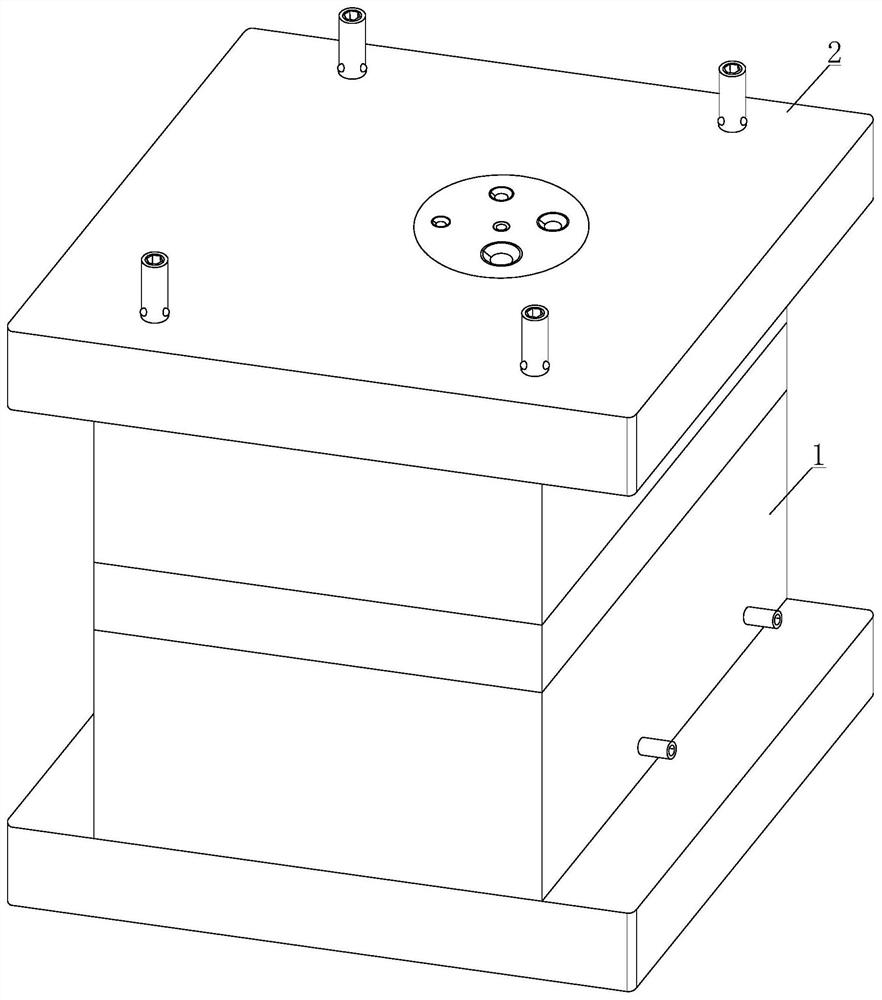
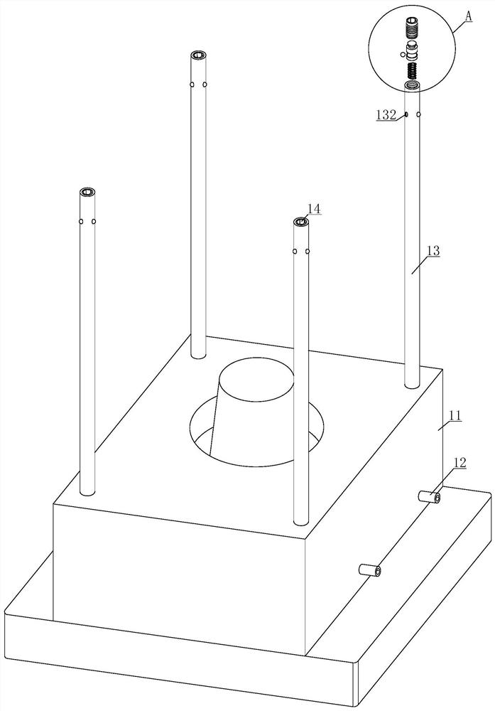
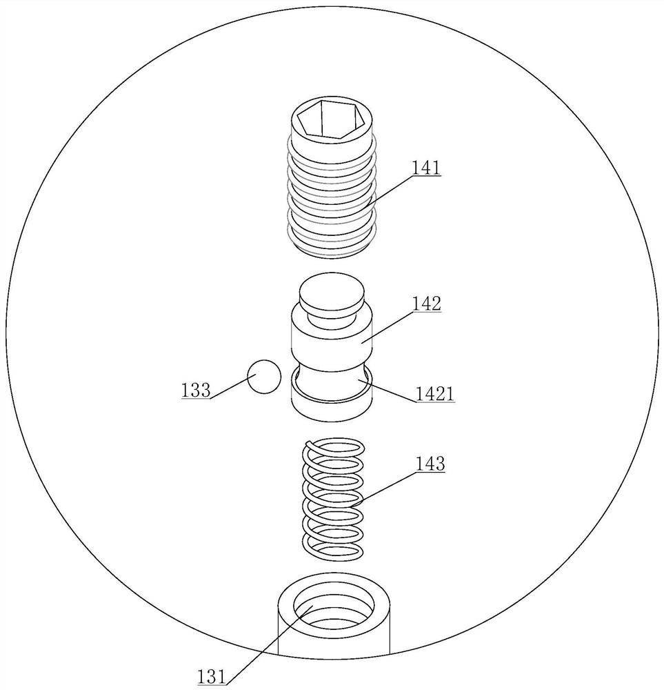
[0033] see Figure 1-3, an injection mold with multi-diameter adjustment, including a first mold 1 and a second mold 2, the lower end of the first mold 1 is equipped with a second mold 2, the first mold 1 includes a bottom mold 11, a cooling hole 12, a positioning rod 13. The positioning rod 13 includes a threaded hole 131, a bead hole 132 and a positioning bead 133. The upper end of the positioning rod 13 is provided with a threaded hole 131. The outer surface of the positioning rod 13 is provided with a bead hole 132. The inner cavity of the bead hole 132 is equipped with a positioning bead. 133, the fixing device 14, the fixing device 14 includes a threaded column 141, a limiting column 142 and a first spring 143, the bottom surface of the threaded column 141 is equipped with a limiting column 142, the lower end of the limiting column 142 is equipped with a first spring 143, and the limit The side of the positioning column 142 is provided with an arc groove 1421, and the fi...

Embodiment 2

[0035] see Figure 4 , the second mold 2 includes a movable mold 21, a buffer plate 22, an adjustment assembly 23 and a positioning hole 24, a buffer plate 22 is installed on the lower end of the movable mold 21, an adjustment assembly 23 is installed on the upper end of the movable mold 21, and the four corners of the upper end of the movable mold 21 A positioning hole 24 is opened.

Embodiment 3

[0037] see Figure 5-6 , the movable mold 21 includes a fixed assembly 211, the fixed assembly 211 includes a rotating plate 2111, a triangular block 2112 and a second spring 2113, one end of the cavity of the fixed assembly 211 is movably installed with a rotating plate 2111, and one end of the rotating plate 2111 is installed with a triangular block 2112 , the other end of the rotating plate 2111 is installed with a second spring 2113, a first limit assembly 212, the first limit assembly 212 includes a third spring 2121 and a first limit groove 2122, and the inner cavity of the first limit assembly 212 is installed There is a third spring 2121, and a first limiting groove 2122 is provided on the inner cavity wall of the first limiting component 212. When the turntable 231 rotates to adjust the injection holes 2311 with different R-angle diameters, the ratchet 2312 installed on the side of the turntable 231 will move together. Rotate, the injection hole 2311 rotates countercl...


PUM


Abstract

The invention discloses an injection mold with multi-aperture adjustment. The injection mold comprises a first mold body and a second mold body, wherein the second mold body is installed at the lowerend of the first mold body, when a bottom mold body and a movable mold body need to be assembled for injection molding, a connecting column can be pressed downwards, a spring column installed at the lower end of the connecting column can move downwards at the same time, an adjusting plate descends along the side wall of a rotating groove while the spring column moves downwards, when the connectingcolumn moves to the bottom end, the adjusting plate is moved out of the rotating groove, the rotating column installed on the back face of the adjusting plate can enable the adjusting plate to rotatetowards one side under the elastic twisting of a torsional spring, the spring column reversely drives the adjusting plate to move upwards under pushing by elastic force of a third spring, the adjusting plate moves along the arc-shaped surface of the rotating groove while the adjusting plate upwards moves, a rotating plate rotates under movement of the adjusting plate, so that injection molding holes with different R-angle diameters are rotationally adjusted to the upper ends of a material injection hole, and the injection molding holes with different R-angle diameters can adapt to injection molding of different material pipes.

Description

technical field [0001] The invention relates to the technical field of injection molds, in particular to an injection mold with multi-diameter adjustment. Background technique [0002] Injection molding is a processing method used in the mass production of certain complex-shaped parts, and is mainly used in the industrial field. The process of injection molding is to inject the heated and melted material into the mold cavity by high pressure, and after cooling and solidifying, a molded product is obtained. The mold is mainly composed of pouring system, molding parts and structural parts. Among them, the gating system is also called the runner system, which is a group of feeding channels that guide the plastic melt from the nozzle of the injection machine to the cavity. It is usually composed of a main channel, a runner, and a gate. A passage from the machine nozzle to the runner or the cavity. The entrance of the main channel is connected to the nozzle of the injection mol...

Claims


Application Information

Patent Timeline
Patent Type & Authority Applications(China)
IPC IPC(8): B29C45/27B29C45/17B29C45/64
CPCB29C45/1756B29C45/2708B29C45/64
Inventor 韩中军
Owner 温州乾牧机械设备有限公司
Why Eureka
Try Eureka