
Novel hub motor driving system

A hub motor and drive system technology, which is applied in the direction of wheels, motion deposition, power devices, etc., can solve the problems of axle and chassis structure changes, occupying limited space on the inner wheels, and poor heat and heat dissipation effects, etc., so as to increase the service life and improve The cruising range and the effect of improving the transmission efficiency

Pending Publication Date: 2021-03-16
YANTAI UNIV
View PDF1 Cites 0 Cited by
  • Summary
  • Abstract
  • Description
  • Claims
  • Application Information

AI Technical Summary

Problems solved by technology

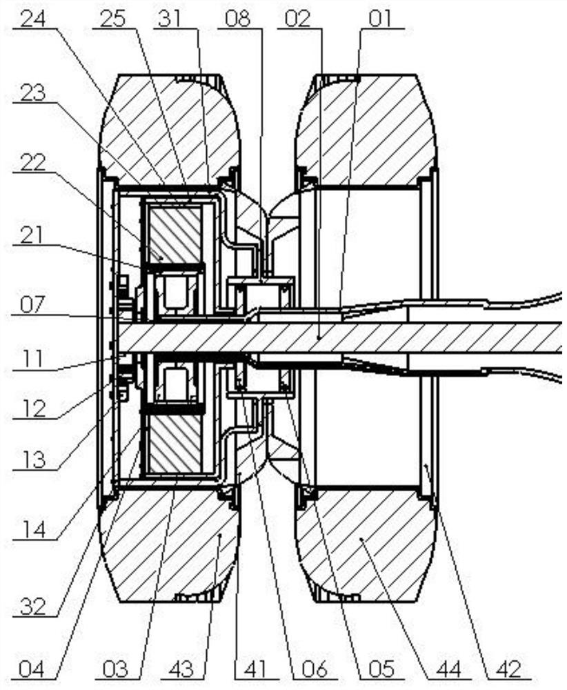
However, the above-mentioned patent solution adopts the integration of the hub motor and the brake inside the inner hub. On the one hand, the driving device, braking device and deceleration mechanism are installed in a limited space at the same time, which will not only reduce the space occupied by the motor. The output power of the motor will directly lead to serious heating and poor heat dissipation, which will easily reduce the service life of the hub motor and brake; on the other hand, in its patented solution, because the hub motor is installed in the inner wheel, it cannot be installed on the outer wheel. so that the planetary gear reducer mechanism is also installed in the inner wheel in order to cooperate with the hub motor, which not only occupies the limited space of the inner wheel, but also has a very large change in the applied axle and chassis structure, which greatly Increase the difficulty of research and development
[0006] The patent "a hub motor integrated system" (patent number: 108749556A), its patented technology distributes the hub motor, braking device, and deceleration mechanism in the inner and outer hubs, but its technical solution sets the reducer and brake on the outer wheel The structure of the original truck axle and chassis has been greatly changed

Method used


Image

  • Novel hub motor driving system
  • Novel hub motor driving system
  • Novel hub motor driving system

Examples


Embodiment 1

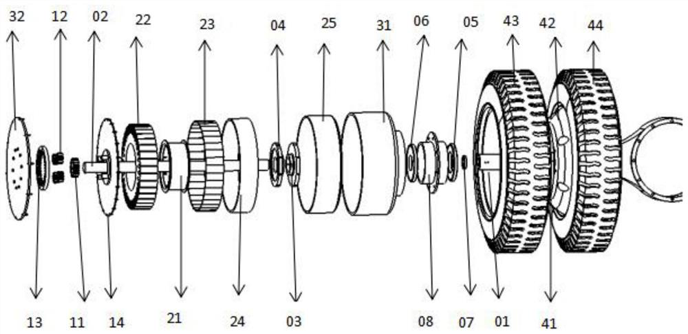
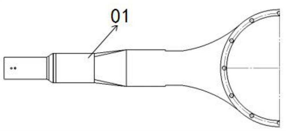
[0042] Such as Figure 1-14 As shown, this embodiment provides a new type of hub motor drive system, which can be used for hybrid or pure electric trucks, buses, engineering vehicles, etc., including hub motors, reducers, wheels and axle housings 01; hub motors and reducers are both Installed in the wheel, the axle housing 01 is located in the middle of the wheel; the hub motor is installed on the axle housing, the hub motor is connected to the reducer, and the outer side of the axle housing 01 is provided with a groove, which is used to allow the wire to pass through to supply power to the hub motor; the wheel rotates Installed on the axle housing 01, the reducer is connected to the wheels to drive the wheels to rotate; a half shaft is also rotated in the axle housing, one end of the half shaft is used to connect with the engine, and the other end passes through the axle housing to connect with the reducer.

[0043] In this embodiment, the in-wheel motor includes a sleeve 21, a...

Embodiment 2

[0054] This embodiment is an improvement made on the basis of Embodiment 1. The improvement is that the planetary gear reducer adopts a two-stage planetary gear reducer to perform two-stage reduction; specifically, the sun gear, planetary gear, ring gear and The planetary disc carrier is provided with two groups. The sun gear of the second-stage planetary gear is installed on the planetary disc carrier 14 of the first-stage planetary gear. After the planetary disc carrier 14 of the first-stage planetary gear is driven by the motor casing 25, it continues to drive The sun gear of the second-stage planetary gear realizes two-stage reduction; the planetary disc carrier of the second-stage planetary gear is fixedly connected with the motor casing 25 through bolts.

[0055] Further, the planetary gear reducer can also be provided with multiple stages as required.


PUM


Abstract

The invention discloses a novel hub motor driving system, and relates to the technical field of driving systems. The novel hub motor driving system can comprise a hub motor, a speed reducer, wheels and an axle housing; the hub motor and the speed reducer are installed in the wheels, and the axle housing is located in the middles of the wheels; the hub motor is installed on the axle housing and connected with the speed reducer, and a groove is formed in the outer side of the axle housing and used for allowing an electric wire to pass through to supply power to the hub motor; the wheels are rotationally installed on the axle housing, and the speed reducer is connected with the wheels and used for driving the wheels to rotate; a half shaft is further rotationally installed in the axle housing, one end of the half shaft is used for being connected with an engine, and the other end of the half shaft penetrates through the axle housing to be connected with the speed reducer. Three working modes including an engine driving mode, a pure electric deceleration driving mode and a hybrid driving mode can be formed, energy can be recycled by controlling the motor, and fuel consumption can be reduced.

Description

technical field [0001] The invention relates to the technical field of drive systems, in particular to a novel hub motor drive system. Background technique [0002] With the development of electric vehicle technology and the application of hub motors, using hub motors as power sources to drive trucks has become a considerable development direction for trucks. Currently, pure electric trucks use motors to transmit power to drive axles through drive shafts. , There is a large amount of energy loss in the process of power mechanical transmission, which affects the cruising range. The driving force of the wheel hub motor combined with the driving force of the traditional engine is used to drive the wheels after deceleration and torque increase through the planetary gear reducer. A hybrid system can be formed on the basis of the existing fuel truck, and the power system of the centralized drive pure electric truck can also be integrated. Further enhance the electric driving forc...

Claims


Application Information

Patent Timeline
Patent Type & Authority Applications(China)
IPC IPC(8): B60K7/00B60K17/04B60B35/18B60B35/14
CPCB60K7/0007B60K17/046B60B35/18B60B35/14B60K2007/0092B60K2007/0038
Inventor 王其光李玉梅马国清冯居辉刘淑敏
Owner YANTAI UNIV
Learn More