Electric power engineering rush-repair combined operation vehicle

A technology of joint operation and power engineering, applied in the directions of overhead line/cable equipment, lifting equipment safety device, hoisting device, etc., can solve the problems of rigid movement and adjustment of work ladders, low power repair efficiency, etc.

Inactive Publication Date: 2021-03-16
国网河北省电力有限公司正定县供电分公司 +2
View PDF9 Cites 4 Cited by
  • Summary
  • Abstract
  • Description
  • Claims
  • Application Information

AI Technical Summary

Problems solved by technology

[0004] Based on the technical problems of the existing joint operation vehicle for emergency repair of electric power engineering, the movement adjustment of the operation ladder is relatively rigid, and the efficiency of electric emergency repair is low, the invention proposes a combined operation vehicle for emergency repair of electric power engineering

Method used


Image

  • Electric power engineering rush-repair combined operation vehicle
  • Electric power engineering rush-repair combined operation vehicle
  • Electric power engineering rush-repair combined operation vehicle

Examples


Embodiment 1

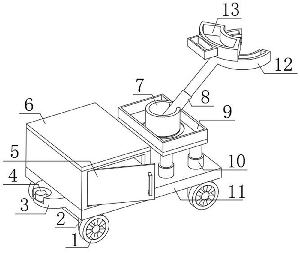
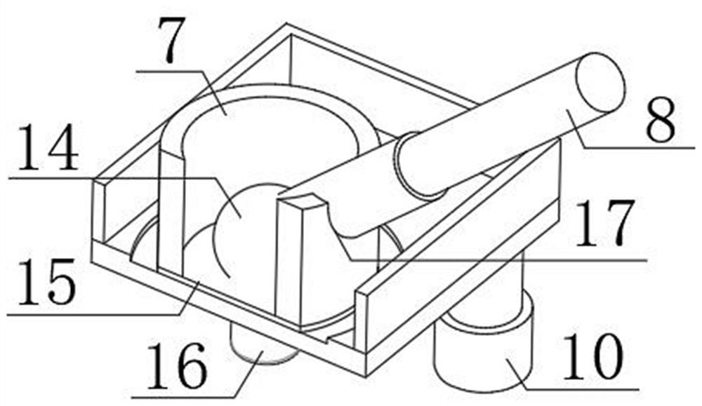
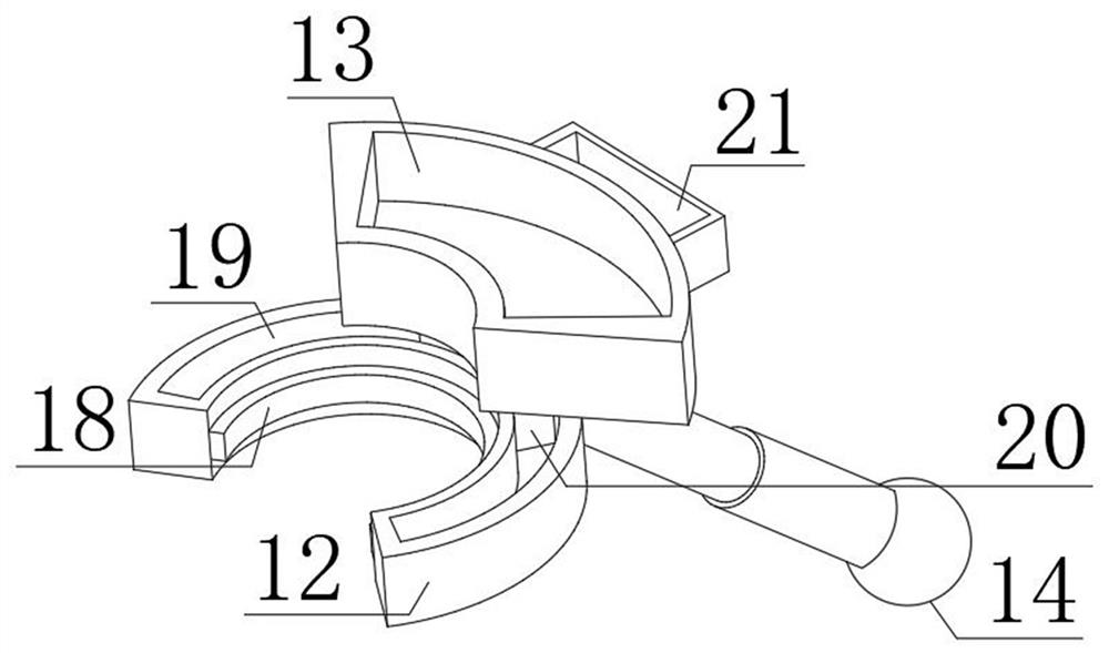
[0025] refer to Figure 1-4 , a combined operation vehicle for electric power engineering emergency repair, comprising a compartment floor 11, one side of the top outer wall of the compartment floor 11 is fixedly connected with four electric telescopic rods 10 distributed equidistantly, and one end of the extension rods of the four electric telescopic rods 10 is fixedly connected with Same fixed table 9, the central position of fixed table 9 top outer wall is provided with rotating disk 15, is fixedly connected with fixed frame 7 on the top outer wall of rotating disk 15, is provided with universal adjustment ball head 14 on the bottom inner wall of fixed frame 7, fixed frame 7 is provided with a limit groove 17 on one side of the outer wall, and a hydraulic rod 8 is fixedly connected to one side of the universal adjustment ball head 14. One end of the extension rod of the hydraulic rod 8 is fixedly connected to an adjustment frame 12, and the top outer wall of the adjustment f...

Embodiment 2

[0033] refer to Figure 5 , a combined operation vehicle for electric power engineering emergency repair, comprising a compartment floor 11, one side of the top outer wall of the compartment floor 11 is fixedly connected with four electric telescopic rods 10 distributed equidistantly, and one end of the extension rods of the four electric telescopic rods 10 is fixedly connected with Same fixed table 9, the central position of fixed table 9 top outer wall is provided with rotating disk 15, is fixedly connected with fixed frame 7 on the top outer wall of rotating disk 15, is provided with universal adjustment ball head 14 on the bottom inner wall of fixed frame 7, fixed frame 7 is provided with a limit groove 17 on one side of the outer wall, and a hydraulic rod 8 is fixedly connected to one side of the universal adjustment ball head 14. One end of the extension rod of the hydraulic rod 8 is fixedly connected to an adjustment frame 12, and the top outer wall of the adjustment fra...


PUM


Abstract

The invention discloses an electric power engineering rush-repair combined operation vehicle. The problems that an existing operation vehicle is stiff in movement adjustment and low in electric powerrush-repair efficiency are solved. According to the following scheme, the electric power engineering rush-repair combined operation vehicle comprises a carriage bottom plate. Four electric telescopicrods which are equidistantly distributed are fixedly connected to one side of the outer wall of the top of the carriage bottom plate, a same fixed table is fixedly connected to one ends of extension rods of the four electric telescopic rods, a rotary disc is arranged in the center of the outer wall of the top of the fixing table, a fixing frame is fixedly connected to the outer wall of the top ofthe rotary disc, a universal adjusting ball head is arranged on the inner wall of the bottom of the fixing frame, and a limiting groove is formed in the outer wall of one side of the fixing frame. A telegraph pole is matched with a sliding block and a sliding rail at the top of the adjusting frame, so that an operation high platform rotates around the telegraph pole, the repairing range can be adjusted more flexibly, and workers are prevented from going up and down in the repairing process to adjust the direction in a matched mode.

Description

technical field [0001] The invention relates to the technical field of electric power engineering, in particular to a combined operation vehicle for emergency repair of electric power engineering. Background technique [0002] At present, electric power engineering refers to engineering related to the production, transmission, and distribution of electric energy. In a broad sense, it also includes engineering that uses electricity as power and energy in various fields. At the same time, it can be understood that the power transmission and transformation industry expansion project. After the 20th century, the production of electric energy mainly relies on thermal power plants, hydropower plants and nuclear power plants. Where conditions permit, tidal, geothermal and wind energies are also used to generate electricity. The transmission and distribution of electric energy is mainly realized through high and low voltage AC power networks. As the development direction of power...

Claims


Application Information

Patent Timeline
Patent Type & Authority Applications(China)
IPC IPC(8): B66F11/04B66F13/00B66F17/00H02G1/02
CPCB66F11/046B66F13/00B66F17/006H02G1/02
Inventor 赵凤忠李洪涛张海滨杜建宇张需峰常丽芳李娜柴秀楚李嗣龙郭静
Owner 国网河北省电力有限公司正定县供电分公司
Why Eureka
Try Eureka