
Cooling device of compressor

A cooling device and compressor technology, applied in the field of compressors, can solve the problems of heat concentration and inability to dissipate, the strength of the oil film is reduced, and the space is limited, so as to achieve the effects of improving the circulating cooling efficiency, improving the service life, and having a simple and reasonable structure.

Inactive Publication Date: 2021-03-16
ANHUI KEHAI COMPRESSOR MFG
View PDF6 Cites 0 Cited by
  • Summary
  • Abstract
  • Description
  • Claims
  • Application Information

AI Technical Summary

Problems solved by technology

[0002] When transporting natural gas, compressors are often used for compression processing; when the compressor is running at high speed, the friction between parts will generate heat, which will increase the temperature of the compressor lubricating oil, and if the lubricating oil temperature is too high, the strength of the oil film will decrease, causing The lubricating effect deteriorates, which leads to faster wear between parts and shortens the service life of the compressor. In order to reduce the temperature of the lubricating oil in the compressor, a shell and tube cooler is often used to cool down; but the existing shell and tube cooler It is installed inside the compressor, and there are many parts inside the compressor, and the space is limited, resulting in the heat being concentrated inside the compressor and unable to dissipate. The cooling water in the shell and tube cooler is affected by the heat inside the compressor, and the temperature will rise , which in turn reduces the cooling efficiency of the cooling water on the lubricating oil, and the temperature of the lubricating oil cannot drop rapidly

Method used


Image

  • Cooling device of compressor
  • Cooling device of compressor
  • Cooling device of compressor

Examples


Embodiment

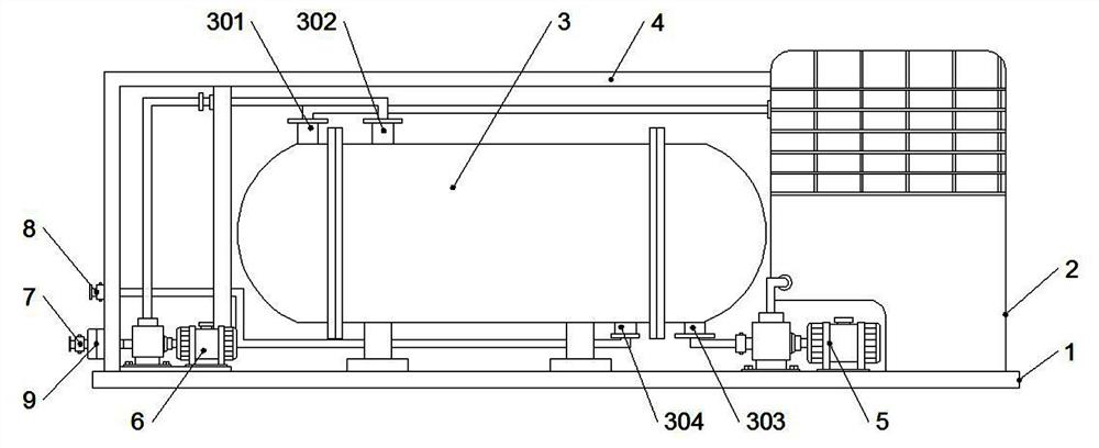
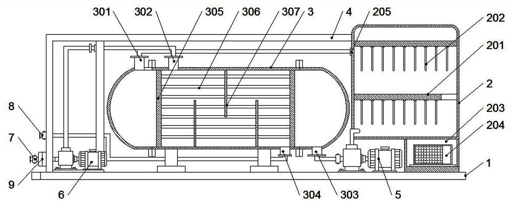
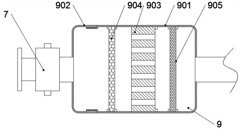
[0019] Example: such as Figure 1-3 As shown, a cooling device for a compressor of the present invention includes an installation base plate 1, a cooling tank 2 and a heat exchange tank 3 are fixedly installed on the top of the installation base plate 1, and a plurality of groups of fixing tanks are fixed horizontally inside the cooling tank 2. frame 201, and the bottom of each group of the fixed frames 201 are vertically fixed with a number of refrigeration fins 202, the inside of the heat exchange tank 3 is respectively fixed with tube plates 305 near both ends, and is covered by the tube plates 305 It is divided into a water inlet chamber, a heat exchange chamber and a water outlet chamber. There are multiple sets of heat exchange tubes 306 fixedly connected horizontally between the tube plates 305 . The cooling liquid inlet 301 and the hot oil inlet 302 are respectively fixedly installed on the side, and the left and right sides of the heat exchange tank 3 near the bottom ...


PUM


Abstract

The invention discloses a cooling device of a compressor. The cooling device comprises a mounting bottom plate, a cooling tank and a heat exchange tank are fixedly mounted at the top end of the mounting bottom plate, a plurality of sets of fixing frames are horizontally and fixedly mounted in the cooling tank, and a plurality of refrigeration pieces are vertically and fixedly mounted at the bottomof each set of fixing frames. Tube plates are fixedly installed on the portions, close to the two ends, in the heat exchange tank respectively. The heat exchange tank is internally divided into a water inlet cavity, a heat exchange cavity and a water outlet cavity by the tube plates, a plurality of sets of heat exchange tubes are horizontally and fixedly connected between the tube plates, and a cooling liquid inlet and a hot oil inlet are fixedly formed in the portions, close to the top end of the tube plate at one end, on the left side and the right side of the heat exchange tank respectively. A cold oil outlet and a cooling liquid outlet are fixedly formed in the portion, close to the bottom end of the tube plate at the other end, on the left side and the right side of the heat exchangetank respectively. The cooling device of the compressor is simple and reasonable in structure, novel in design, easy to operate, capable of effectively cooling lubricating oil in the compressor and high in practical value.

Description

technical field [0001] The invention relates to the technical field of compressors, in particular to a compressor cooling device. Background technique [0002] When transporting natural gas, compressors are often used for compression processing; when the compressor is running at high speed, the friction between parts will generate heat, which will increase the temperature of the compressor lubricating oil, and if the lubricating oil temperature is too high, the strength of the oil film will decrease, causing The lubricating effect deteriorates, which leads to faster wear between parts and shortens the service life of the compressor. In order to reduce the temperature of the lubricating oil in the compressor, a shell and tube cooler is often used to cool down; but the existing shell and tube cooler It is installed inside the compressor, and there are many parts inside the compressor, and the space is limited, resulting in the heat being concentrated inside the compressor and ...

Claims


Application Information

Patent Timeline
Patent Type & Authority Applications(China)
IPC IPC(8): F16N39/02F16N39/06F04B39/02
CPCF04B39/02F16N39/02F16N39/06F16N2039/007
Inventor 吴狄汪长波
Owner ANHUI KEHAI COMPRESSOR MFG
Learn More