
Low temperature-seepage coupling dynamic impact compression experiment device for frozen rock-soil body

An experimental device and technology of rock and soil mass, applied in the field of dynamic shock compression, can solve the problems of indoor experimental research on dynamic shock compression characteristics of rock and soil without freezing, unable to truly reflect dynamic mechanical properties, and no research and development of frozen dynamic shock experimental device.

Pending Publication Date: 2021-03-16
ZHEJIANG UNIVERSITY OF SCIENCE AND TECHNOLOGY
View PDF0 Cites 0 Cited by
  • Summary
  • Abstract
  • Description
  • Claims
  • Application Information

AI Technical Summary

Problems solved by technology

In the actual excavation environment of artificially frozen rock and soil engineering, it is an environmental field coupled with multiple fields of temperature field and seepage field, and it is also a dynamic impact disturbance process. Construction loads, vehicle loads, artificial excavation loads and other dynamic load disturbances, and the existing research is mainly to carry out static indoor uniaxial and triaxial tests, numerical simulation tests and physical simulations under the action of a single low-temperature temperature field and seepage field Experiments, etc., cannot truly reflect the dynamic mechanical properties of rock and soil in the environment where the rock and soil occur. Field multi-field coupling freeze dynamic shock experimental device

Method used


Image

  • Low temperature-seepage coupling dynamic impact compression experiment device for frozen rock-soil body
  • Low temperature-seepage coupling dynamic impact compression experiment device for frozen rock-soil body
  • Low temperature-seepage coupling dynamic impact compression experiment device for frozen rock-soil body

Examples


Embodiment

[0045] Design and implementation principle of the present invention are:

[0046] Generally speaking, the seepage field is constructed first, then the low-temperature temperature field is constructed, and finally the dynamic impact compression experiment of frozen rock and soil under the coupling of the seepage field and the low-temperature temperature field is carried out. details as follows:

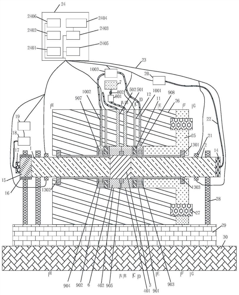
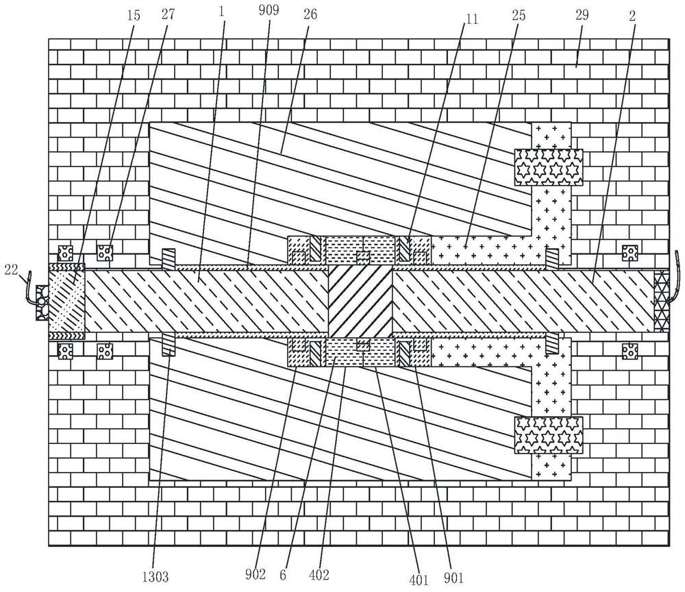
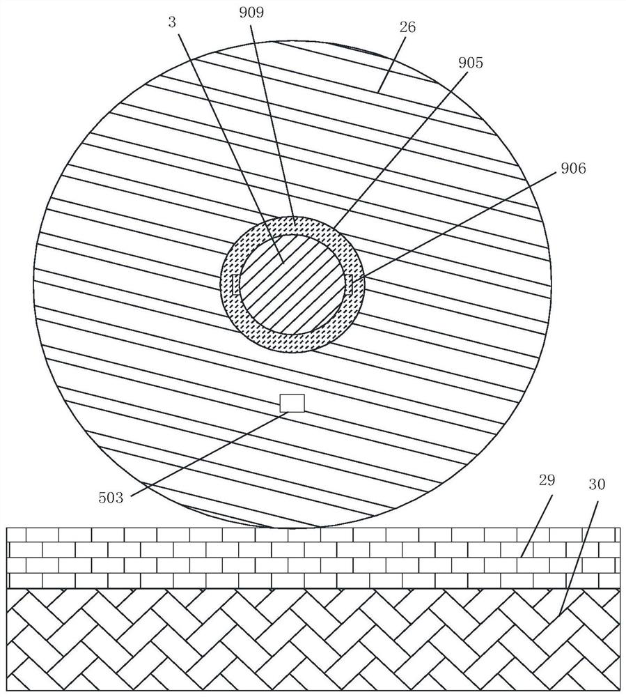
[0047] 1. Seepage field construction: through Hydraulic Loading and Storage Systems The water inlet hole 1001 in the hydraulic load storage system 9 injects pressurized pure water 909 into the first hydraulic storage hole 901 in the hydraulic load storage system 9, and then flows into the first water flow input groove 903 through the water jet hole 907, and then flows through the axial flow of the central axis The input tank 906 is sequentially input into the axial longitudinal water flow input tank 905 and the second water flow input tank 904, so that the pressurized pure water 909 ...


PUM

PropertyMeasurementUnit
heightaaaaaaaaaa

Abstract

The invention discloses a low temperature- seepage coupling dynamic impact compression experiment device for a frozen rock-soil body. Dynamic impact compression mechanical experiments are carried outon various freezing damage characteristics of the frozen rock-soil body in different low-temperature temperature field and seepage field coupling environments. The device comprises a rock-soil body sample, a bracket system, a freezing system, a hydraulic load and storage system, a dynamic impact system and a comprehensive control system. The bracket system comprises an L-shaped ring type flange, aload protection sleeve, a fastening bolt, a stabilizing support, a horizontal fixing frame and a foundation, the L-shaped ring type flange is connected with the load protection sleeve, and the bottomof the load protection sleeve is welded to the horizontal fixing frame; the horizontal fixing frame is in threaded connection with the foundation; the freezing system comprises a circular ring type freezing system, a liquid nitrogen pipeline system, liquid nitrogen, a liquid nitrogen storage tank and a liquid nitrogen flow pressure system; the circular ring type freezing system is a hollow cylindrical structure; and the rock-soil body sample is arranged in the center of the interior of the circular ring type freezing cavity system and is in a cylinder shape.

Description

technical field [0001] The application belongs to the technical field of dynamic impact compression of frozen rock and soil mass. Background technique [0002] The freezing damage caused by low-temperature freezing of rock and soil not only involves the freezing expansion damage of rock and soil, but also involves the multi-field coupling of temperature field and seepage field in low temperature environment, which seriously threatens the safety and stability of artificial freezing engineering and rock and soil engineering in cold regions. . In particular, the artificial freezing method is widely used in the construction of subway communication passages. The low temperature-seepage coupling characteristics of rock and soil, as well as freezing temperature, freezing thickness, frost heaving pressure, and engineering disturbance are important prerequisites for ensuring the safety of construction projects. During the artificial freezing process, when fissure water exists inside...

Claims


Application Information

Patent Timeline
Patent Type & Authority Applications(China)
IPC IPC(8): G01N3/307G01N3/02
CPCG01N3/02G01N3/307G01N2203/001G01N2203/0044G01N2203/0228G01N2203/0236
Inventor 邹宝平牟军东易觉刘治平吕明豪胡力绳罗战友夏建中董涛叶良邝光霖
Owner ZHEJIANG UNIVERSITY OF SCIENCE AND TECHNOLOGY
Learn More