An electrical cabinet device for flood control and dehumidification

A technology for electrical cabinets and electrical appliances, which is applied to electrical equipment shells/cabinets/drawers, circuits, electric switches, etc., and can solve problems such as inability to dehumidify inside electrical cabinets, loss of public property, and potential safety hazards

Active Publication Date: 2022-03-25
上海日盛电气有限公司
View PDF14 Cites 0 Cited by
  • Summary
  • Abstract
  • Description
  • Claims
  • Application Information

AI Technical Summary

Problems solved by technology

[0002] It is very necessary to be moisture-proof and moisture-proof during the use of electrical cabinets. Although some of the electrical cabinets at this stage have the function of moisture-proof and moisture-proof, most of them cannot prevent the invasion of floods, which will cause damage to the internal circuits and cannot be used in continuous rain. Play a good protective role, resulting in the loss of public property, and now most of the electrical cabinets cannot perform good internal dehumidification when it rains, resulting in potential safety hazards when there is moisture inside

Method used


Image

  • An electrical cabinet device for flood control and dehumidification
  • An electrical cabinet device for flood control and dehumidification
  • An electrical cabinet device for flood control and dehumidification

Examples


Embodiment Construction

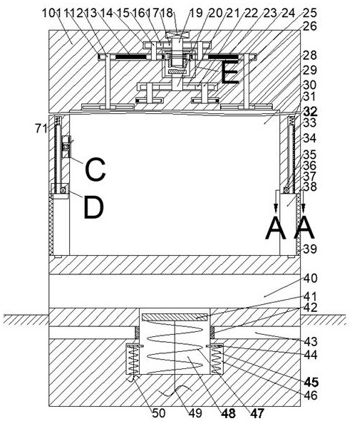
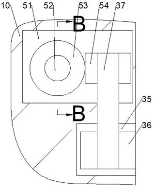
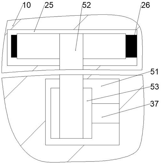
[0019] Combine below Figure 1-6 The present invention is described in detail, wherein, for the convenience of description, the orientations mentioned below are defined as follows: figure 1 The up, down, left, right, front and back directions of the projection relationship itself are the same.

[0020] A flood control and dehumidification electrical cabinet device described in conjunction with accompanying drawings 1-6 includes a main box body 10, a motor 18 is provided inside the main box body 10, and a fan wheel transmission cavity 14 is provided on the lower side of the motor 18. A clutch chamber 66 is provided on the lower side of the fan wheel transmission chamber 14, and a fan wheel pulley chamber 11 is arranged symmetrically around the center of the clutch chamber 66 on the left and right sides of the clutch chamber 66. The lower side of the clutch chamber 66 is The side is provided with a clutch transmission chamber 24, and the lower side of the clutch transmission ch...


PUM


Abstract

The invention relates to the related field of electrical cabinets, and discloses a flood control and dehumidification electrical cabinet device, which includes a main box body, a motor is arranged in the main box body, a fan wheel transmission chamber is arranged on the lower side of the motor, and a fan wheel transmission chamber is arranged on the lower side of the fan wheel transmission chamber. Clutch chamber, the left and right sides of the clutch chamber are provided with fan pulley chambers arranged symmetrically with the clutch chamber as the center, the clutch transmission chamber is provided on the lower side of the clutch chamber, and two The left and right symmetrical clutch transmission belt senses the rise of the external water potential through the descending distance of the hydraulic pressure block, and under the drive of the clutch pull rope, it affects the meshing relationship between the clutch slider and the power-off friction block cavity, so as to indirectly affect the flood control. The opening and closing relationship between the plate and the flood control cooling chamber, so as to control the opening and closing timing of the flood control device, and when the external water potential is too high, the hydraulic pressure block will drive the movement of the power-off slider, thereby driving the movement of the power-off friction block , so as to achieve the purpose of disconnecting the main power switch to protect the power supply.

Description

technical field [0001] The invention relates to the related field of electrical cabinets, in particular to an electrical cabinet device for flood control and dehumidification. Background technique [0002] It is very necessary to be moisture-proof and moisture-proof during the use of electrical cabinets. Although some of the electrical cabinets at this stage have the function of moisture-proof and moisture-proof, most of them cannot prevent the invasion of floods, which will cause damage to the internal circuits and cannot be used in continuous rain. It plays a good protective role, resulting in the loss of public property, and now most of the electrical cabinets cannot perform good internal dehumidification when it rains, resulting in potential safety hazards when there is moisture inside. Contents of the invention [0003] The object of the present invention is to provide a flood control and dehumidification electrical cabinet device, which can overcome the above-mention...

Claims


Application Information

Patent Timeline
Patent Type & Authority Patents(China)
IPC IPC(8): H05K5/02H05K7/20H01H35/26
CPCH05K5/0217H05K5/0247H05K7/20172H01H35/26
Inventor 孔祥年
Owner 上海日盛电气有限公司
Why Eureka
Try Eureka