
Building waste recycling device

A technology of construction waste and crushing device, which is applied in the directions of magnetic separation, solid separation, grain processing, etc., can solve the problems of unfavorable reuse of other wastes, insufficient crushing of wastes, and inability to recover iron materials separately, so as to facilitate recycling, Speed ​​up discharge efficiency and enhance the effect of vibration

Inactive Publication Date: 2021-03-19
朱志飞
View PDF15 Cites 4 Cited by
  • Summary
  • Abstract
  • Description
  • Claims
  • Application Information

AI Technical Summary

Problems solved by technology

[0002] With the acceleration of urbanization, the rapid development of urban reconstruction and construction industry, coupled with the aging of some old buildings and urban infrastructure and the expiration of service life, more and more civil engineering construction projects are scrapped and demolished, and then A large amount of construction demolition waste is generated, and construction waste contains a large amount of reusable materials such as bricks or reinforced concrete. If it is not processed and utilized again, it will inevitably cause waste of resources. However, the existing construction waste recycling devices are still There are the following deficiencies: 1. The traditional construction waste recovery device has a poor crushing effect on the waste, which leads to the incomplete crushing of the waste, and the waste needs to be crushed many times, which affects the work efficiency; 2. Most of the waste recovery devices cannot The iron material in the waste is recycled separately, which causes a great waste of resources and is not conducive to the reuse of other waste materials; therefore, we propose a construction waste recycling device

Method used

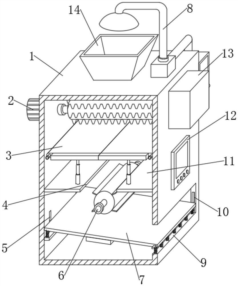

Image

  • Building waste recycling device
  • Building waste recycling device
  • Building waste recycling device

Examples


Embodiment Construction

[0027] In order to make the technical means, creative features, goals and effects achieved by the present invention easy to understand, the present invention will be further described below in conjunction with specific embodiments.

[0028] In the description of the present invention, it should be noted that the terms "upper", "lower", "inner", "outer", "front end", "rear end", "both ends", "one end", "another end" The orientation or positional relationship indicated by etc. is based on the orientation or positional relationship shown in the drawings, and is only for the convenience of describing the present invention and simplifying the description, rather than indicating or implying that the referred device or element must have a specific orientation, use a specific Azimuth configuration and operation, therefore, should not be construed as limiting the invention. In addition, the terms "first" and "second" are used for descriptive purposes only, and should not be understood ...


PUM


Abstract

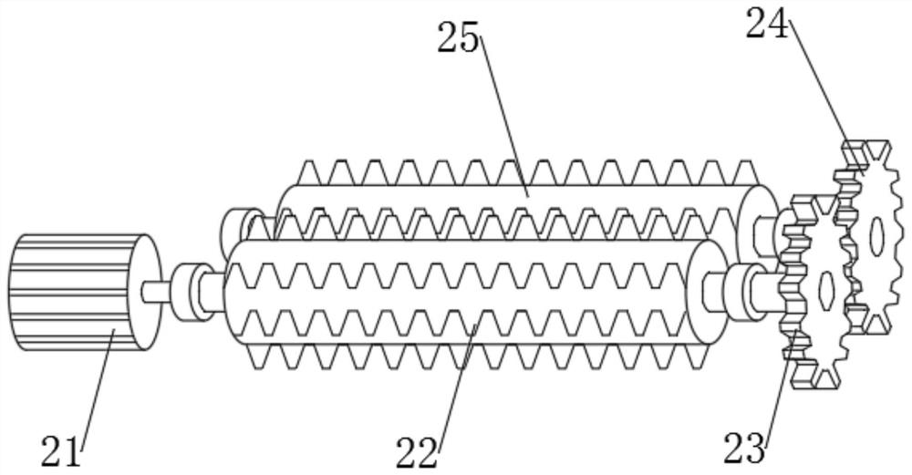
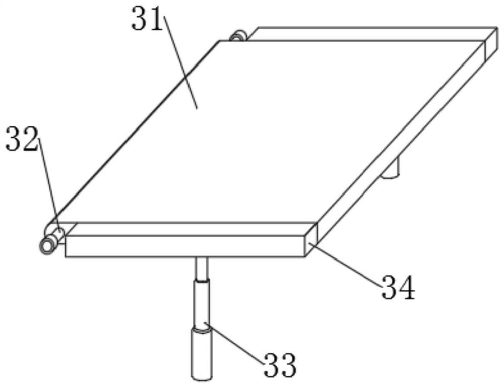
The invention discloses a building waste recycling device which comprises a box body, a smashing device is movably connected to the upper portion of the left end of the box body in a penetrating and inserting mode, and two discharging devices are jointly and movably connected between the upper portion of the front box wall and the upper portion of the rear box wall of the box body. An iron attracting device is movably connected between the lower portion of the front box wall and the lower portion of the rear box wall of the box body jointly, two first limiting grooves are formed in the lower portion of the left box wall of the box body, a discharging opening is formed in the lower portion of the right end of the box body, and second limiting grooves are formed in the middle of the front opening wall and the middle of the rear opening wall of the discharging opening. A discharging device is movably connected into the two second limiting grooves and the two first limiting grooves jointly, a controller is fixedly connected to the middle of the right end of the box body, and a dust suction device is fixedly connected to the upper portion of the rear end of the box body. The whole building waste recycling device is good in building waste smashing effect, recycling of waste is facilitated, iron can also be screened out, and the building waste recycling device is suitable for being widely applied.

Description

technical field [0001] The invention relates to the technical field of construction equipment, in particular to a construction waste recycling device. Background technique [0002] With the acceleration of urbanization, the rapid development of urban reconstruction and construction industry, coupled with the aging of some old buildings and urban infrastructure and the expiration of service life, more and more civil engineering construction projects are scrapped and demolished, and then A large amount of construction demolition waste is generated, and construction waste contains a large amount of reusable materials such as bricks or reinforced concrete. If it is not processed and utilized again, it will inevitably cause waste of resources. However, the existing construction waste recycling devices are still There are the following deficiencies: 1. The traditional construction waste recovery device has a poor crushing effect on the waste, which leads to the incomplete crushing...

Claims


Application Information

Patent Timeline
Patent Type & Authority Applications(China)
IPC IPC(8): B02C4/08B02C4/28B02C23/08B03C1/02
CPCB02C4/08B02C4/28B02C23/08B02C2201/06B03C1/02
Inventor 朱志飞
Owner 朱志飞
Learn More