Cleaning equipment for electronic electromechanical assembly production

A technology for electromechanical components and cleaning equipment, applied in the direction of cleaning methods using liquids, cleaning methods and utensils, chemical instruments and methods, etc., can solve problems such as workpiece damage, and achieve the effect of precise washing

Inactive Publication Date: 2021-03-19
权旭彤
View PDF0 Cites 2 Cited by
  • Summary
  • Abstract
  • Description
  • Claims
  • Application Information

AI Technical Summary

Problems solved by technology

[0005] The purpose of the present invention is to solve the problems in the prior art that the cleaning equipment for the production of electronic electromechanical components cleans the workpiece by manually operating the high-pressure nozzle. Due to the impact force of the high-pressure nozzle, the workpiece is moved by the impact force, and multiple workpieces are stacked together. , the friction and impact between multiple workpieces will cause damage to the workpieces, and a cleaning equipment for the production of electronic electromechanical components is proposed

Method used


Image

  • Cleaning equipment for electronic electromechanical assembly production
  • Cleaning equipment for electronic electromechanical assembly production
  • Cleaning equipment for electronic electromechanical assembly production

Examples


Embodiment 1

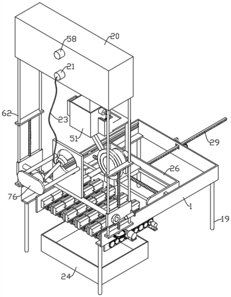
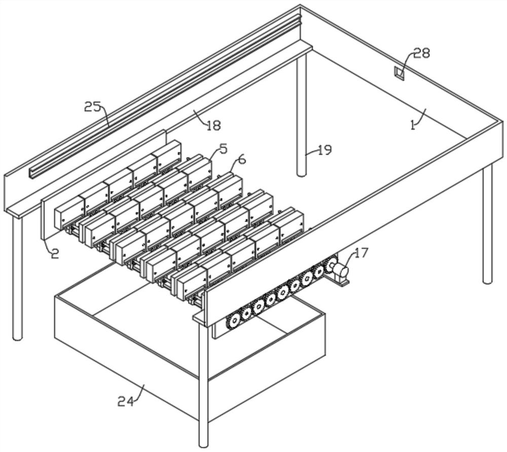
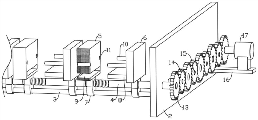
[0027] refer to Figure 1-12 , a cleaning device for the production of electronic electromechanical components, including a U-shaped frame 1, a clamping assembly is arranged in the U-shaped frame 1, the clamping assembly includes two side plates 2 distributed at intervals, and the side plate 2 on one side is provided with There is a driving mechanism, and a plurality of equidistantly distributed clamping mechanisms are arranged between the two side plates 2. The clamping mechanism includes a first guide rod 3, a first screw rod 4 and a plurality of equidistantly distributed clamping units. The two ends of a guide rod 3 are respectively fixedly connected to the side plates 2 on both sides, the thread lines on the first screw mandrel 4 are discontinuously distributed, the thread lines on the first screw mandrel 4 are equidistantly distributed into multiple sections, and the first screw mandrel 4 4 Both ends are rotatably installed on the side plates 2 on both sides, the clamping...

Embodiment 2

[0031] Considering the realization of automatic feeding and flushing, it is not necessary to manually place the workpieces 80 between the movable plate 5 and the fixed plate 6, and at the same time realize the automatic flushing of the nozzles 22, and multiple workpieces 80 can be flushed without manual operation of the nozzles 22.

[0032] refer to Figure 1-12 , as another preferred embodiment of the present invention, the difference from Embodiment 1 is that a directional feeding mechanism is provided on the top side of the U-shaped frame 1, and the directional feeding mechanism includes two slide rails 25, and the two slide rails 25 are fixedly installed respectively. On both sides in the U-shaped frame 1, a U-shaped frame 26 is arranged between two slide rails 25, and a slide block 27 is fixedly installed on both sides of the U-shaped frame 26, and the slide block 27 is respectively slidably arranged in the slide rail 25, and the U-shaped frame 26 is fixedly mounted on bot...


PUM


Abstract

The invention relates to the technical field of cleaning equipment, in particular to cleaning equipment for electronic electromechanical assembly production. The cleaning equipment comprises a U-shaped frame and a water tank, wherein a clamping assembly is arranged in the U-shaped frame; the clamping assembly comprises two side plates which are distributed at an interval; a driving mechanism is arranged on the side plate on one side; a plurality of clamping mechanisms which are distributed at equal intervals are arranged between the two side plates; each clamping mechanism comprises a first guide rod, a first lead screw and a plurality of clamping units distributed at equal intervals; the driving mechanism comprises a plurality of first gears; reversing transmission gears are arranged between every two adjacent first gears; a first motor base is fixedly mounted on one side plate; a first motor is fixedly mounted on the first motor base; a booster pump is fixedly mounted on the water tank; and the water outlet end of the booster pump is communicated with a nozzle. Workpieces can be clamped between movable plates and fixed plates, and an operator aligns the nozzle with the workpiecesone by one for washing, so that the workpieces cannot move in the washing process.

Description

technical field [0001] The invention relates to the technical field of cleaning equipment, in particular to a cleaning equipment for the production of electronic electromechanical components. Background technique [0002] Flux and solder paste are usually used as soldering auxiliary materials before electronic components are packaged. These soldering auxiliary materials will have some residues during the soldering process, including fingerprints, sweat, horny and dust contaminated during the manufacturing process. and other pollutants. [0003] For high-speed connectors belonging to electronic components, the physical appearance of high-speed connectors can refer to the drawings in the manual Figure 11 As shown, the cleaning methods of electronic and electromechanical components are mainly divided into two types. One is to directly clean the workpiece through a high-pressure nozzle, and use a special cleaning agent to wash away the stains on the workpiece. The other is to u...

Claims


Application Information

Patent Timeline
Patent Type & Authority Applications(China)
IPC IPC(8): B08B3/02B08B13/00
CPCB08B3/02B08B13/00
Inventor 不公告发明人
Owner 权旭彤
Why Eureka
Try Eureka