Weld-line movement-controlled tailor-welded blank stamp-forming device

A technology for stamping and tailor-welded blanks, which is applied in the direction of fluid pressure actuators, servo motors, mechanical equipment, etc., and can solve problems such as inability to flexibly control the blank-holding force of the sheets on both sides of the weld

Inactive Publication Date: 2012-01-04
HARBIN INST OF TECH
View PDF6 Cites 10 Cited by
  • Summary
  • Abstract
  • Description
  • Claims
  • Application Information

AI Technical Summary

Problems solved by technology

[0003] The present invention aims to solve the problem that the existing tailor welded blank stamping forming device cannot control the movement of the weld seam by adjusting the blank holder force of the block blank holder and adjusting the clamping force of the weld seam because there is no block blank holder. The problem of controlling the blank holder force on the sheets on both sides of the weld seam, and then providing a tailor welded blank stamping forming device that controls the movement of the weld seam

Method used


Image

  • Weld-line movement-controlled tailor-welded blank stamp-forming device
  • Weld-line movement-controlled tailor-welded blank stamp-forming device
  • Weld-line movement-controlled tailor-welded blank stamp-forming device

Examples


specific Embodiment approach 1

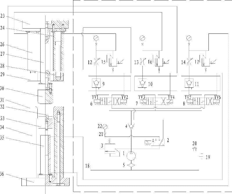
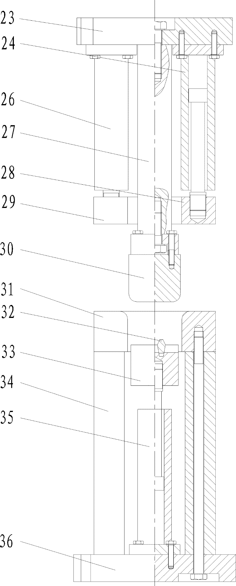
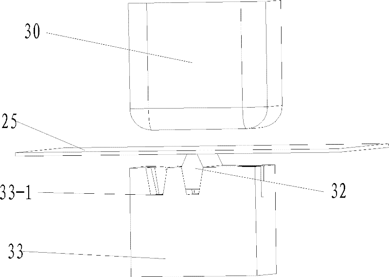
[0013] Specific implementation mode one: as Figure 1-7 As shown, the Tailored Welded Blank Stamping Device for Controlling Weld Seam Movement in this embodiment includes a die device, a hydraulic system and a control system, and the die device includes an upper template 23, a first hydraulic cylinder 24, and a second hydraulic cylinder 26 , connecting column 27, punch 30, block blank holder ring, die 31, clamping pin 32, clamp block 33, third hydraulic cylinder 35, two die pads 34 and lower template 36, block blank holder The ring is composed of a first blankholder ring 28 and a second blankholder ring 29. Two die pads 34 are respectively fixed on both sides of the upper end surface of the lower template 36. The third hydraulic cylinder 35 is located between the two die pads 34 and the second The bottom end of the cylinder body of the three hydraulic cylinders 35 is fixed on the upper end surface of the lower template 36, the die 31 is installed on the upper end surfaces of t...

specific Embodiment approach 2

[0014] Specific implementation mode two: as Figure 1~5 As shown, in this embodiment, a draw bead 42 is provided on the lower end surface of the first blank holder 28 or the second blank holder 29, and a draw bead groove 43 is provided at a corresponding position on the upper end surface of the die 31, so The drawbead 42 is matched with the drawbead groove 43 . The above technical measures can further control the flow of sheet metal on both sides of the tailor welded blank weld. Other components and connections are the same as those in the first embodiment.

specific Embodiment approach 3

[0015] Specific implementation mode three: as Figure 1~5 As shown, the hydraulic system in this embodiment includes a hydraulic pump 1, a reversing valve 2, a relief valve 3, a check valve 4, a filter 5, an oil tank 18, a first hydraulic unit, a second hydraulic unit and a third hydraulic unit. Unit; the first hydraulic unit includes the first electromagnetic reversing valve 6, the first hydraulic control check valve 9, the first throttle valve 12 and the first proportional overflow valve 15; the second hydraulic unit includes the second electromagnetic reversing valve 7. The second hydraulic control check valve 10, the second throttle valve 13 and the second proportional overflow valve 16; the third hydraulic unit includes the third electromagnetic reversing valve 8, the third hydraulic control check valve 11, the third The throttle valve 14 and the third proportional relief valve 17; the hydraulic pump 1 is installed in the oil tank 18, the relief valve 3 is installed on th...


PUM


Abstract

The invention discloses a weld-line movement-controlled tailor-welded blank stamp-forming device, relating to tailor-welded blank stamp-forming devices. The weld-line movement-controlled tailor-welded blank stamp-forming device aims at solving the problem that the traditional tailor-welded blank stamp-forming device cannot control a weld line to move to a correct position through regulating a blank-holding force of a blocking blank holder and regulating a holding force of the weld line and cannot flexibly control a blank-holding force on a blank at two sides of the weld line. A female die is mounted on the upper end faces of two female die cushions; a holding block can move up and down along the die cavity of the female die under the driving of a piston rod of a third hydraulic cylinder; a holding pin inserts into one of grooves; a first blank holder and a second blank holder are arranged above the female die and are used for positioning a tailor-welded blank; the upper end face of the first blank holder is connected with a piston of a first hydraulic cylinder; the upper end face of the second blank holder is connected with a piston of a second hydraulic cylinder; and a control system is used for adjusting the motion of the three hydraulic cylinders through controlling the on/off of each hydraulic valve component in a hydraulic system. According to the invention, the inflow volume of blanks at the two sides of the weld line of the tailor-welded blank can be effectively controlled.

Description

technical field [0001] The invention relates to a stamping and forming device for tailor welded blanks, which belongs to the technical field of stamping and forming of tailor welded blanks. Background technique [0002] The different combinations of plates on both sides of the tailor welded blank make the formability, bearing capacity and geometric shape of the tailor welded blank different. The weld often moves during the stamping forming process. meet actual needs. Chinese patent 02257820.X (publication number: CN 2584341Y) adopts a punch with a stepped surface and a blank holder and uses a nitrogen cylinder to generate clamping force to control the movement of the weld seam. This method can indeed control the welding seam very well. The welding seam moves during the stamping forming process of the welded plate, but the time stability is low, and there is a high requirement for the position accuracy of the plate placed on the mold before stamping forming, so it is not eas...

Claims


Application Information

Patent Timeline
Patent Type & Authority Applications(China)
IPC IPC(8): B21C37/02F15B11/16
Inventor 胡秀丽党修成
Owner HARBIN INST OF TECH
Why Eureka
Try Eureka