Wood block punching forming equipment for building materials

A technology for forming equipment and wood blocks, applied in wood stamping, stationary drilling machines, etc., can solve the problems of different length and angle of punched holes, complicated storage, different strength and angle, etc.

Active Publication Date: 2021-03-19
谈备
View PDF10 Cites 6 Cited by
  • Summary
  • Abstract
  • Description
  • Claims
  • Application Information

AI Technical Summary

Problems solved by technology

[0004] In order to overcome the different punching strength and angles of the workers each time they use the drill bit, which will lead to different lengths and angles of the punched holes and affect the use, and the workers also need to carry the punched wood blocks to the designated location for storage. However, the technical problem to be solved is: to provide a method that can e

Method used


Image

  • Wood block punching forming equipment for building materials
  • Wood block punching forming equipment for building materials
  • Wood block punching forming equipment for building materials

Examples


Example Embodiment

[0052] Example 1

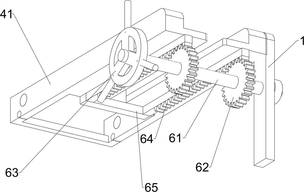
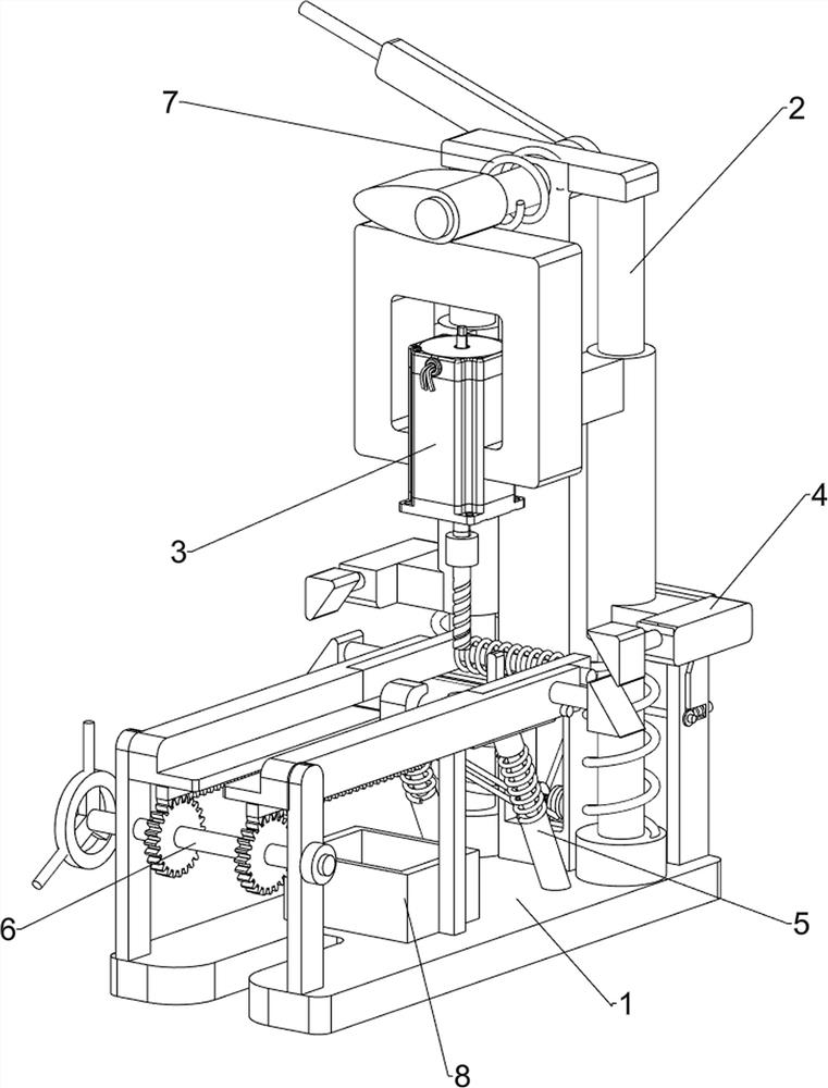
[0053] A kind of wood block punching and forming equipment for building materials, such as figure 1 , figure 2 , image 3 , Figure 4 , Figure 5 and Image 6 As shown, it includes a base plate 1, a pressing mechanism 2, a punching mechanism 3, a clamping mechanism 4 and a blanking mechanism 5. Hole mechanism 3, clamping mechanism 4 is installed on the front side of base plate 1 top and pressing mechanism 2, and base plate 1 top rear side is provided with blanking mechanism 5, and blanking mechanism 5 is positioned at pressing mechanism 2 below.

[0054]When a worker needs to punch and form a wooden block, the worker first needs to place the wooden block on the clamping mechanism 4. After the wooden block is placed on the clamping mechanism 4 by the worker, the worker needs to press down on the pressing mechanism with his left hand 2. The downward movement of the pressing mechanism 2 will drive the punching mechanism 3 to slide downward, and the downw...

Example Embodiment

[0055] Example 2

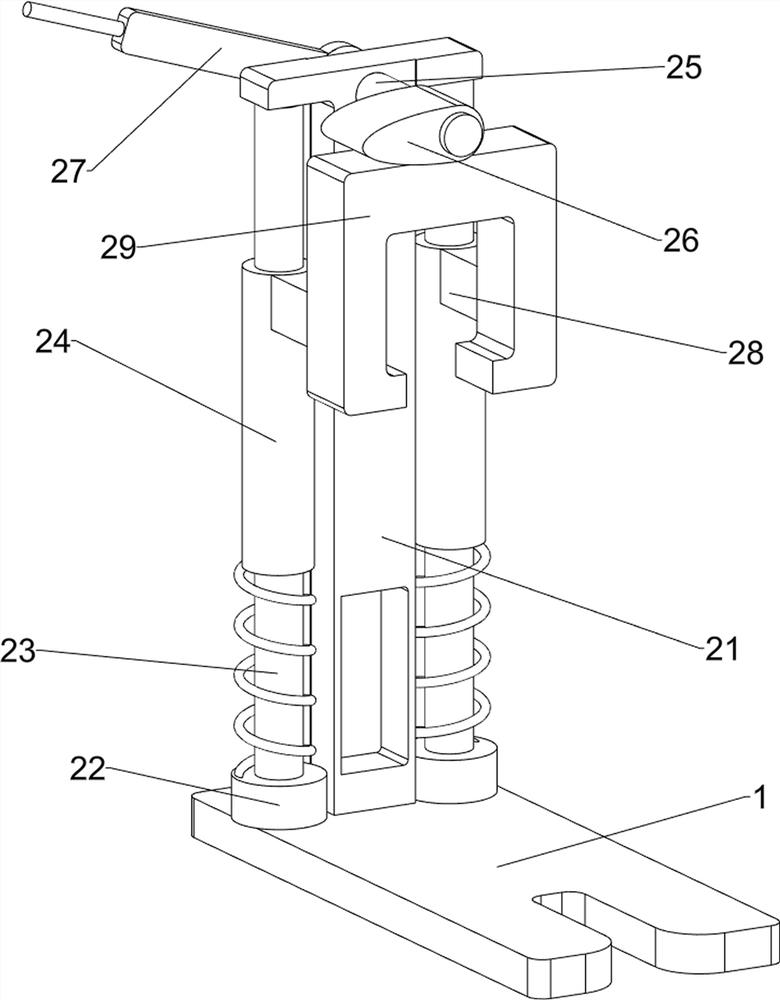
[0056] In a preferred embodiment of the present invention, as figure 1 , figure 2 , image 3 , Figure 4 , Figure 5 and Image 6 As shown, the pressing mechanism 2 includes a fixed plate 21, a first fixed sleeve 22, a guide rod 23, a first elastic member 24, a first rotating shaft 25, a cam 26, a handle 27, a first fixed block 28 and a second fixed block 29. A fixing plate 21 is fixedly connected to the middle of the top rear side of the bottom plate 1. The first fixing sleeve 22 is symmetrically provided on the rear side of the top of the bottom plate 1. The first fixing sleeve 22 is located on the left and right sides of the fixing plate 21. The top of the first fixing sleeve 22 All are welded with guide rods 23, and the guide rods 23 are all slidably provided with a first elastic member 24, and the top of the fixed plate 21 is rotatably provided with a first rotating shaft 25, and the front end of the first rotating shaft 25 is welded with a cam 26...

Example Embodiment

[0058] Example 3

[0059] In a preferred embodiment of the present invention, as figure 1 , figure 2 , image 3 , Figure 4 , Figure 5 , Image 6 and Figure 7 As shown, the punching mechanism 3 includes a servo motor 31, a second fixed sleeve 32 and a drill bit 33, the middle of the bottom of the second fixed block 29 is fixedly connected with a servo motor 31 by bolts, and the output shaft of the servo motor 31 is sleeved with a second fixed Cover 32, the drill bit 33 is affixed to the bottom of the second fixed sleeve 32.

[0060] Before the worker presses the handle 27 downwards, the worker needs to start the servo motor 31 to rotate earlier, the rotation of the servo motor 31 will drive the drill bit 33 to rotate, and when the second fixed block 29 moves downward, the second fixed block 29 will drive the servo motor 31 and Drill bit 33 moves downwards, and drill bit 33 rotates and can carry out punching molding work to block, when second fixed block 29 moves upw...


PUM


Abstract

The invention relates to punching forming equipment, in particular to wood block punching forming equipment for building materials. The technical problem to be solved is to provide the wood block punching forming equipment for building materials, it can be guaranteed that the lengths and the angles of punched holes of all wood blocks are the same, meanwhile, the punched wood blocks can slide to designated positions to be stored at intervals, workers can be assisted in pushing the wood blocks towards one side, and the use safety of the whole equipment is improved. According to the technical scheme, the wood block punching forming equipment for building materials comprises a bottom plate, a punching mechanism and a punching mechanism, wherein a pressing mechanism is arranged on one side of the top of the bottom plate; and the punching mechanism is arranged on the pressing mechanism in a sliding manner. According to the wood block punching forming equipment for building materials, the pressing mechanism is arranged, the pressing mechanism is matched with the punching mechanism, punching work can be conducted on the wood blocks, and meanwhile the pressing mechanism and a discharging mechanism can carry the punched wood blocks to the designated positions to be stored.

Description

technical field [0001] The invention relates to punching and forming equipment, in particular to a punching and forming equipment for wooden blocks used as building materials. Background technique [0002] At present, most real estate developers generally use wooden blocks in construction projects. Due to the needs of use, workers will punch and form wooden blocks. In the prior art, workers generally use drills to punch wooden blocks for building materials. Work, the strength and angle of each drill used by the workers are different, which will lead to different lengths and angles of the punched holes and affect the use, and the workers also need to carry the wood blocks after the punched holes to the designated location for storage. Complex lock. [0003] In view of the fact that the strength and angle of the above-mentioned workers using the drill bit are different each time, the length and angle of the punched holes will be different and affect the use, and the workers a...

Claims


Application Information

Patent Timeline
IPC IPC(8): B27C3/02B27M1/04
CPCB27C3/02B27M1/04
Inventor 谈备
Owner 谈备
Why Eureka
Try Eureka