
Seam plugging equipment for steel structure engineering

A steel structure and engineering technology, which is applied in building construction, building maintenance, construction, etc., can solve problems such as secondary damage, increase the man-hours of caulking operations, and the impact of filler strength, etc., to achieve a firm bonding effect

Inactive Publication Date: 2021-03-19
华东栋
View PDF6 Cites 0 Cited by
  • Summary
  • Abstract
  • Description
  • Claims
  • Application Information

AI Technical Summary

Problems solved by technology

However, the existing method has the following disadvantages: due to the presence of gas in the gap, air bubbles are easily formed in the filler, and part of the gap cannot be completely filled due to the effect of air pressure, therefore, it has a certain impact on the strength of the filler
[0004] The above is an explanation of how to fill the gaps specifically, but the sealing blocks and other devices mentioned therein do not mention what kind of material they are. This involves whether they can adapt to gap sealing with different outer contours. At the same time, after the plugging block is plugged and the gap is filled with slurry, how to completely separate the plugging block from the cured slurry is a problem. After the separation, can the plugging block itself guarantee a certain Integrity, whether it can be used for two or more times. At the same time, the cured slurry will be damaged twice by the method mentioned in the above plan. At this time, it is necessary to operate on the damaged surface, which will increase the caulking operation. working hours

Method used


Image

  • Seam plugging equipment for steel structure engineering
  • Seam plugging equipment for steel structure engineering
  • Seam plugging equipment for steel structure engineering

Examples


Embodiment Construction

[0040] Below in conjunction with accompanying drawing and embodiment of description, specific embodiment of the present invention is described in further detail:

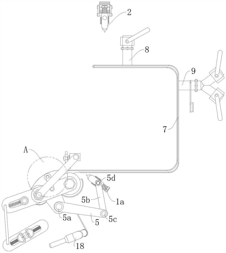
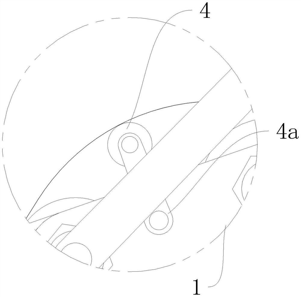
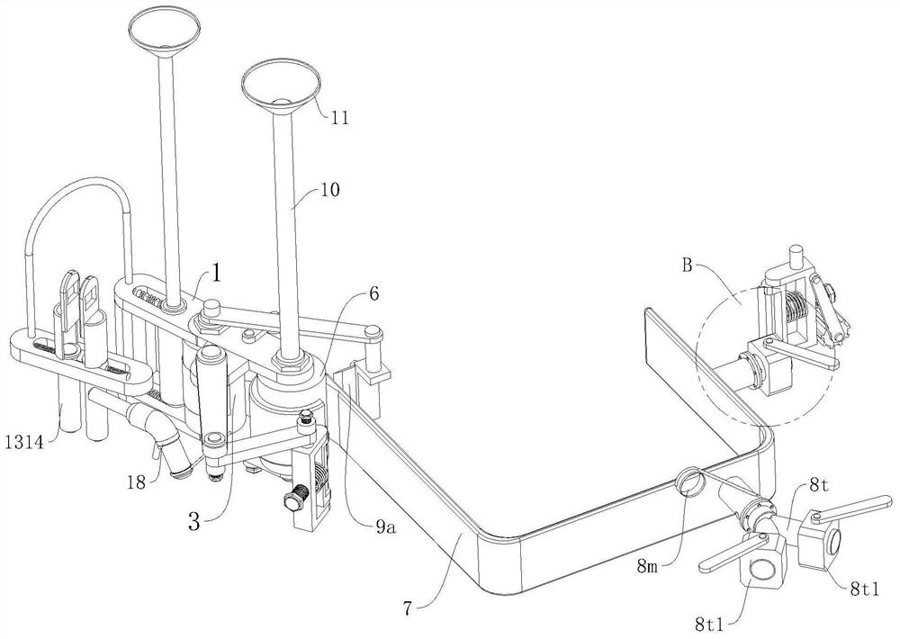
[0041] refer to Figure 1 to Figure 10 A kind of caulking equipment for steel structure engineering shown includes a first clamp 1a, a second clamp 2, a mounting bracket 1, a film tube 3, an unwinding steel tube 6 and a sealing rubber 7, and the film tube 3 and The unwinding steel cylinders 6 are all vertical and symmetrically hinged in the mounting bracket 1. A compression cylinder 3a is provided on the side of the film cylinder 3. The compression cylinder 3a can be arranged directly towards or away from the film cylinder 3 through an elastic device. The rubber 7 is a hollow structure, one end of the sealing rubber 7 is wound on the unwinding steel cylinder 6, and the other end of the sealing rubber 7 is provided with an expansion air pipe 8 and a mediation pipe 9, and the expansion air pipe 8 is connected with the...


PUM


Abstract

The invention relates to the field of steel structure engineering equipment, in particular to seam plugging equipment for steel structure engineering. The seam plugging equipment comprises a first clamping device, a second clamping device, an installing bracket, a thin film cylinder, an unwinding steel cylinder and sealing rubber, wherein the thin film cylinder and the unwinding cylinder are symmetrically hinged in the installing bracket, a pressing cylinder is arranged beside the thin film cylinder, the sealing rubber is of a hollow structure, one end of the sealing rubber is wound around theunwinding steel cylinder, the other end of the sealing rubber is provided with an expansion air pipe and a medium passing pipe, the expansion air pipe communicates with the interior of the sealing rubber, the medium passing pipe penetrates through the sealing rubber, a rotary cutter is arranged beside the medium passing pipe, an adjusting arm is arranged at the bottom of the installing bracket, the first clamping device is connected to the installing bracket through an adjusting arm, the second clamping device is an independent auxiliary piece and is approximately symmetrical with the first clamping device in a working state, a traction roller is arranged outside the installing bracket, and the traction roller is movably connected to the installing bracket through an adjusting bracket. according to the equipment, rapid joint filling can be conducted on gaps of a steel structure, and all the joint filling pieces can be repeatedly used.

Description

technical field [0001] The invention relates to the field of steel structure engineering equipment, in particular to a plugging equipment for steel structure engineering. Background technique [0002] During the construction of steel structures, due to construction and manufacturing tolerances, it is easy to form gaps between steel structures and steel structures, between steel structures and equipment, and between equipment and equipment. For the gap filling problem, in many cases, there is a certain strength requirement after filling the gap. The existing method is to use a high-pressure grouting machine to forcefully inject fillers such as caulking agents into the gaps. However, the existing method has the following disadvantages: due to the presence of gas in the gap, air bubbles are easily formed in the filler, and some positions of the gap cannot be completely filled due to the effect of air pressure, so the strength of the filler is affected to a certain extent. [...

Claims


Application Information

Patent Timeline
Patent Type & Authority Applications(China)
IPC IPC(8): E04G23/02
CPCE04G23/0203E04G23/0211
Inventor 华东栋
Owner 华东栋
Learn More