End-to-end unsupervised optical flow estimation method based on event camera

An unsupervised and event-based technology, applied in the field of computer vision, can solve the problems of raw event data discomfort, energy consumption, and lack of true value of optical flow in raw event data, and achieve the effect of improving network performance

Active Publication Date: 2021-03-19
SOUTHEAST UNIV
View PDF3 Cites 10 Cited by
  • Summary
  • Abstract
  • Description
  • Claims
  • Application Information

AI Technical Summary

Problems solved by technology

Although many algorithms have been proposed for these two parts, there are still many limitations: 1. The original event data is not suitable for conventional CNNs network input, it needs to be preprocessed and converted into a form that can be read by conventional networks, Most of these representation methods are hand-crafted, poor in flexibility and energy-consuming, and cannot obtain suitable representation methods for specific tasks; 2. A large amount of raw event data lacks the true value of optical flow, and cannot complete a supervised optical flow estimation network training; therefore, there is an urgent need for a new solution to the above technical problems

Method used


Image

  • End-to-end unsupervised optical flow estimation method based on event camera
  • End-to-end unsupervised optical flow estimation method based on event camera
  • End-to-end unsupervised optical flow estimation method based on event camera

Examples


Embodiment 1

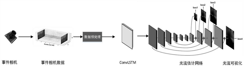
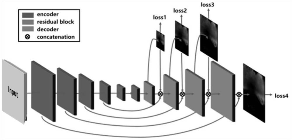
[0025] Example 1: See figure 1 , An end-to-end end-to-end-to-end-to-end-oriented optical current estimation method, such as figure 2 As shown, including the following steps:

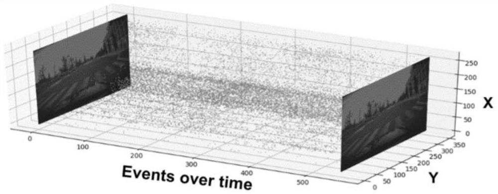
[0026] Step 1. Get the event camera LED Estimation Data Set MVSec, download the ROS BAG raw data set package from the Data Set Homepage, and get event stream data and grayscale frame data. A single event contains coordinates (X, Y), timestamp T e And the event polarity P, grayscale chart contains timestamp T i High h in the image i And wide W i . Event camera output data visualization figure 1 Indicated.

[0027] Step 2, first preprocess the data set: filter out the data before the first frame gradation map, will I ti To i ti+6 The event data between the event is a sample, here the T i It refers to the time corresponding to the gradation frame, and the timestamp of the obtained sample event is converted to normal in seconds, in order to enhance data, the second sample is taken as I t+1 To i t+7 In this cla...


PUM


Abstract

The invention provides an end-to-end unsupervised optical flow estimation method based on an event camera, and relates to the field of optical flow estimation of computer vision. Aiming at overcomingthe defects that event camera data for optical flow estimation lacks a real optical flow value and event data needs to be manually made into event representation in advance, the invention provides anend-to-end unsupervised optical flow estimation method based on an event camera. The method comprises the following steps: preprocessing original data by using event streams output by an event camera,converting four-dimensional data into three-dimensional data, dividing each sample into a plurality of sub-sequences, independently processing each sub-sequence by using ConvLSTM, and splicing the sub-sequences according to channels after all the sub-sequences are processed to form three-dimensional data finally sent into an optical flow prediction network. An optical flow prediction network similar to a coder/decoder is adopted, luminosity error loss is designed by utilizing front and rear gray frames of event flow data output by an event camera at a fixed frequency, and smoothness loss is added to jointly serve as unsupervised loss, so that the network is promoted to finally estimate the optical flow.

Description

Technical field [0001] The present invention relates to an estimation method, and more particularly to an end-to-end-free optical flow estimate based on an event camera, which belongs to the computer visual technology. Background technique [0002] Event camera (Event Camera) is a novel sensor, compared to a conventional camera, is not a fixed frequency capture image, but generates an event based on the change in brightness of the pixel point, and outputs the event stream. The event stream encodes the polarity of the timestamp, position and variation of the brightness, e = {x, y, t, p}, wherein (x, y) represents the coordinate point, T represents the timestamp of the event, P Indicates polarity, value ± 1, "+" indicates the increase in brightness, "-" indicates the brightness decrease, and also outputs a gradation image at a fixed frequency, such as figure 1 Indicated. Event camera has a good performance compared to the traditional camera: high-time resolution (microose level), ...

Claims


Application Information

Patent Timeline
Patent Type & Authority Applications(China)
IPC IPC(8): G06T7/269G06N3/04
CPCG06T7/269G06N3/049G06N3/044
Inventor 刘代坤孙长银陆科林徐乐玏
Owner SOUTHEAST UNIV
Why Eureka
Try Eureka