
PCB of plunger type intank urea pump controller and wiring method thereof

A wiring method and a urea pump technology, which are applied in printed circuit making wiring diagrams, printed circuit manufacturing, printed circuits connected with non-printed electrical components, etc., can solve problems such as crystal oscillator wiring other signal interference, program errors, etc.

Inactive Publication Date: 2021-03-19
NANJING IKAKAT EMISSIONS TECH CO LTD +2
View PDF0 Cites 0 Cited by
  • Summary
  • Abstract
  • Description
  • Claims
  • Application Information

AI Technical Summary

Problems solved by technology

[0005] The object of the present invention is to propose a plunger type intank urea pump controller PCB and its wiring method in order to solve the problem that the existing crystal oscillator wiring is easily interfered by other signals and that program errors are prone to occur during normal operation

Method used


Image

  • PCB of plunger type intank urea pump controller and wiring method thereof
  • PCB of plunger type intank urea pump controller and wiring method thereof

Examples


Embodiment 1

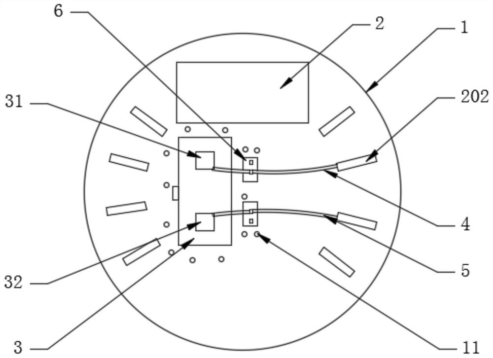
[0033] see figure 1 , a plunger type intank urea pump controller PCB, PCB1 is provided with a microprocessor 2, a crystal oscillator 3, a signal line 4 and a signal line 2 5, and the microprocessor 2 includes a pin 21 and a pin 2 22; the crystal oscillator 3 includes a first pin 31 and a second pin 32; the signal line one 4 connects the first pin 21 to the first pin 31; the signal line two 5 connects the The second pin 22 is connected to the second pin 32; The lengths of the traces between them should be approximately equal, that is, the lengths of the first signal line 4 and the second signal line 5 are approximately equal, and the first signal line 4 and the second signal line 5 are arranged as arcs, so that all The signal provided by the crystal oscillator 3 is more stable;

Embodiment 2

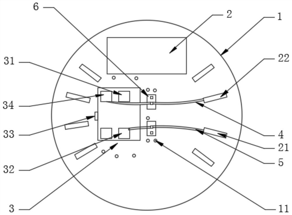
[0035] see figure 2 , figure 2 It is a structural schematic diagram of another embodiment of the PCB of the plunger type intank urea pump controller PCB of the present invention, since the linear distance between the first pin 21 and the first pin 31 is different from that between the pin two 22 to The straight-line distances between the two pins 32 are not equal, therefore, to achieve equal lengths of the signal line one 4 and the signal line two 5, they can be arranged as follows figure 2 The arc shown in Fig. The range of interference can be further narrowed. Compared with the right-angle routing in the prior art, the signal line 1 4 and the signal line 2 5 in the embodiment both follow an arc, which can make the signal transmission effect better;

[0036] In this embodiment, the microprocessor 2 and the crystal oscillator 3 are reasonably wired on the PCB 1 to prevent the signal from being disturbed, so that the plunger type intank urea pump controller PCB frequency,...


PUM


Abstract

The invention discloses a PCB of a plunger type intank urea pump controller and a wiring method thereof. The PCB comprises a PCB body, wherein the PCBbody is provided with a microprocessor, a crystaloscillator, a first signal line and a second signal line. According to the invention, the microprocessor, the crystal oscillator, the first signal line and the second signal line are arranged on the PCB body; the microprocessor comprises a first pin and a second pin; the crystal oscillator comprises a first base pin and a second base pin; the first pin is connected with the first base pin throughthe first signal line; the second pin is connected with the second pin through the second signal wire; the length of the first signal line is equal to the length of the second signal line; and the first signal line and the second signal line are arranged to be arc lines. According to the invention, the microprocessor and the crystal oscillator are reasonably wired on the PCB to prevent signals from being interfered, so the frequency of the PCB of the plunger type intank urea pump controller is reduced, and the program operation of electronic equipment is stable.

Description

technical field [0001] The invention relates to the technical field of a plunger type intank urea pump controller, in particular to a plunger type intank urea pump controller PCB and a wiring method thereof. Background technique [0002] With the development of science and technology, electronic equipment has gradually become popular and entered thousands of households. As long as there is a microprocessor in the electronic equipment, the microprocessor must be provided with a signal by the crystal oscillator before the microprocessor can work normally. Currently, there is a PCB (Printed Circuit Board: printed circuit board) for electronic equipment with a microprocessor. [0003] At present, the requirements for the plunger-type intank urea pump controller PCB are relatively strict. When designing, the wiring of the crystal oscillator is often not taken seriously, and it is considered to be completed when it is only connected, which leaves hidden dangers, especially in high...

Claims


Application Information

Patent Timeline
IPC IPC(8): H05K1/02H05K1/18H05K3/00
CPCH05K1/0228H05K1/18H05K3/0002
Inventor 熊飘洋何俊俊韩丰阳胡德恩田雨林汪旻浩李科许玲玲
Owner NANJING IKAKAT EMISSIONS TECH CO LTD
Learn More