Removably attachable storage device

a storage device and removable technology, applied in the field of items and material storage receptacles, can solve the problems of increasing gripping traction, college campus dormitories are known for limited furniture capacity, and the lack of bedside table space poses a major challenge for students virtually physically linked to their mobile phones

Inactive Publication Date: 2012-08-09
GAWRONSKI JEFFREY STEPHEN
View PDF7 Cites 15 Cited by
  • Summary
  • Abstract
  • Description
  • Claims
  • Application Information

AI Technical Summary

Benefits of technology

[0012]Presented herein is a unique removably attachable storage device configured especially to temporarily secure cell phones and other personal items at a location easily accessed by the user. The storage device described herein as particularly applicable to bedside use where it securely engages a bedpost or other adjacent, generally vertical column or stanchion, and serves to present stored items for immediate retrieval on demand. Obviously, broader application of the disclosed storage device can extend to any stationary fixture or structure suited to its unique interconnection qualities as will be explained below. The unique storage device remains in place without slipping or falling due to the elasticity and anti-slip properties of the material from which it is fabricated.

Problems solved by technology

By force of gravity the device's pliable, elastic material is further stretched causing the attachment opening to be distorted, thereby considerably increasing gripping traction.
As noted above, college campus dormitories are known for limited capacity for furnishings.
A lack of bedside table space poses a major challenge for students virtually physically linked to their mobile phones and similar electronic devices.

Method used


Image

  • Removably attachable storage device
  • Removably attachable storage device
  • Removably attachable storage device

Examples


Embodiment Construction

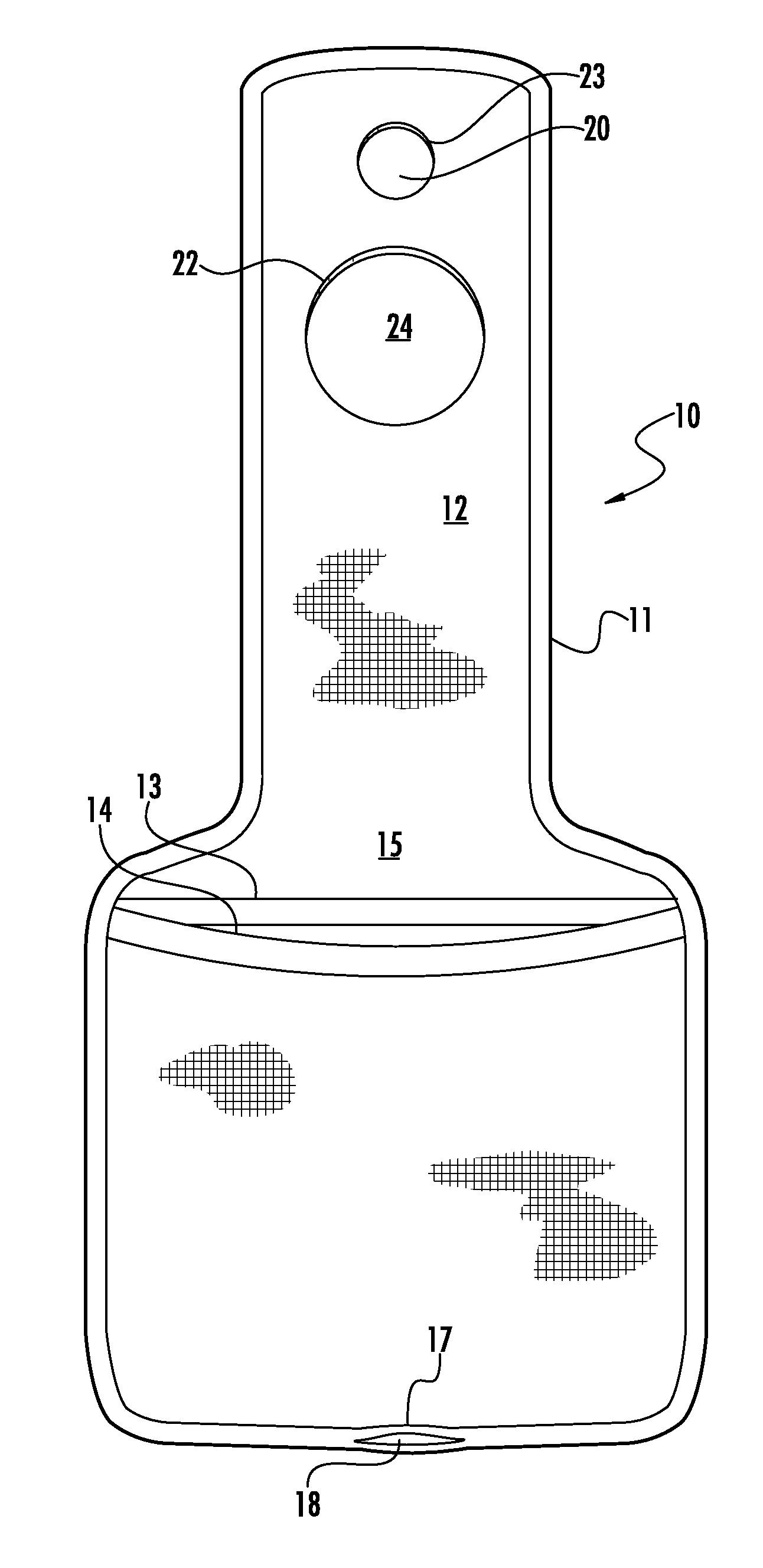
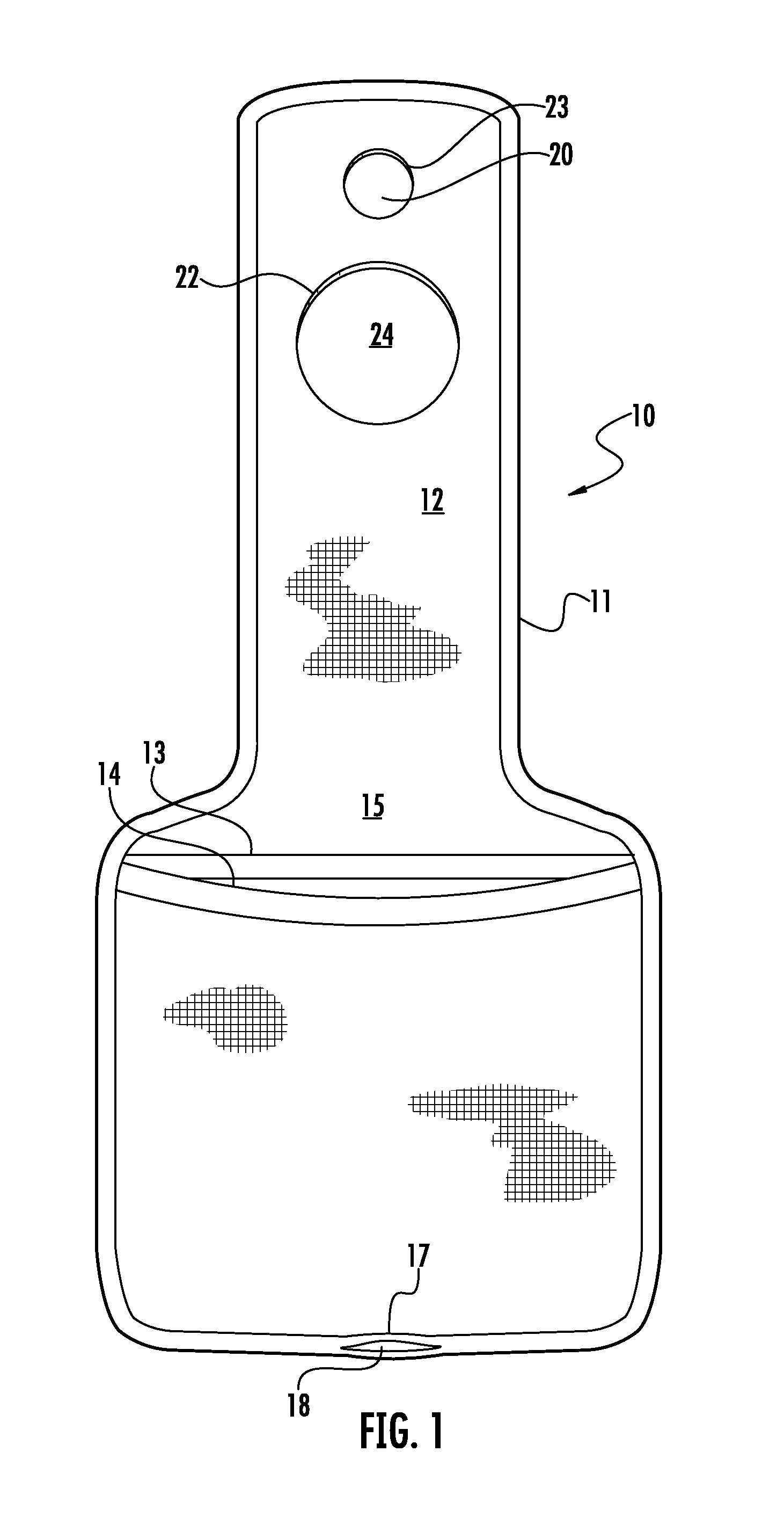
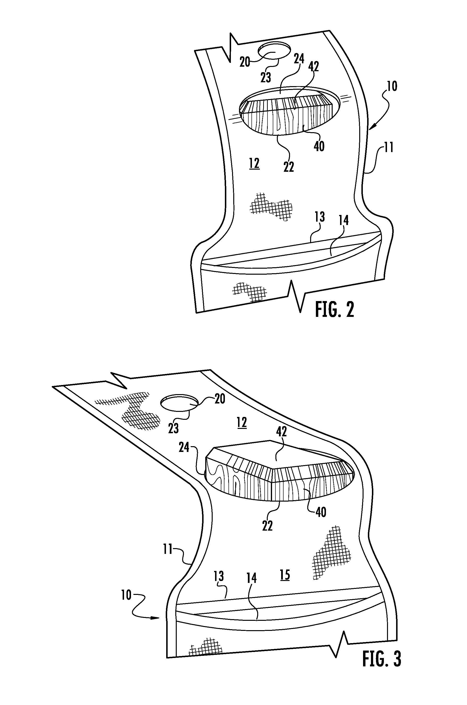
[0022]The removably attachable storage device 10 includes at least two parts, including an attachment portion 12 and storage portion 15 as will be explained. In fabrication, storage portion 15 is configured to define at least one storage zone; by way of example only, the illustrated version of this storage zone presents two defined overlapping storage cavities or pockets 13, 14. These pockets could be side-by-side (not shown), depending on the nature of items to be stored therein. Of course, additional pockets can be defined by adding (partially or fully) overlapping fabric panels suitably sized and configured for specific stored items. Clearly, as depicted, overlapping defined pocket cavities 13, 14 extend generally laterally from edge to edge (11) of said storage portion 15. Defined cavities 13, 14 are formed for temporary and convenient containment of any of a variety of devices and / or relatively small articles as mentioned hereabove.

[0023]At least attachment portion 12 of device...


PUM


Abstract

A temporary storage device fabricated at least in part of memory stretch material (such as synthetic rubber, e.g. polychloroprene material and the like. A storage portion of said device may be fabricated from the same polychloroprene material and is configured with at least one defined storage pocket. An attachment portion of the storage device has defined therein at least one generally annular stretchable opening. This attachment opening, due to the elastically stretchable quality of the device fabric will be stretched sufficiently to surround and cling snugly to a support stanchion such as a bedpost commonly found on a bunk or loft bed. More than one attachment opening of different sizes can be defined in the attachment portion so as to sizably correspond with different posts. The suspended storage device remains in place due to its gripping elasticity as well as gravity pull which distorts and further tightens the elastic opening.

Description

CROSS-REFERENCE TO RELATED APPLICATIONS[0001]The present application claims priority to U.S. Provisional Patent Application Ser. No. 61 / 457,240 filed on Feb. 9, 2011, and entitled “Bunk Pocket,” the disclosure of which is incorporated by reference in its entirety for all purposes, as if fully set forth herein.STATEMENT REGARDING FEDERALLY SPONSORED RESEARCH OR DEVELOPMENT[0002]Not applicableREFERENCE TO SEQUENCE LISTING[0003]Not applicableFIELD OF THE DISCLOSURE[0004]The present disclosure relates generally to item and material storage receptacles. More specifically the present disclosure relates to temporary storage devices for personal items and materials for convenient access.BACKGROUND OF THE DISCLOSURE[0005]The popular use of cell phones has soared throughout the last two decades. These personal devices not only help people stay in touch with family, friends and businesses, they have become a principal link to the outside world. Today, nearly six billion subscribers across the ...

Claims


Application Information

Patent Timeline
Patent Type & Authority Applications(United States)
IPC IPC(8): B65D30/02
CPCA47C7/62A45C2011/002A45F5/00A47C21/00A47C19/22
Inventor GAWRONSKI, JEFFREY STEPHEN
Owner GAWRONSKI JEFFREY STEPHEN
Why Eureka
Try Eureka