

Biological dehydration method for garbage
A biological drying and garbage technology, applied in the direction of solid waste removal, etc., can solve the problem of difficulty in waste gas collection, and achieve the effect of low site requirements, low interference, and non-polluting treatment environment
- Summary
- Abstract
- Description
- Claims
- Application Information
AI Technical Summary
Problems solved by technology
Method used
Image

Examples
Embodiment 1
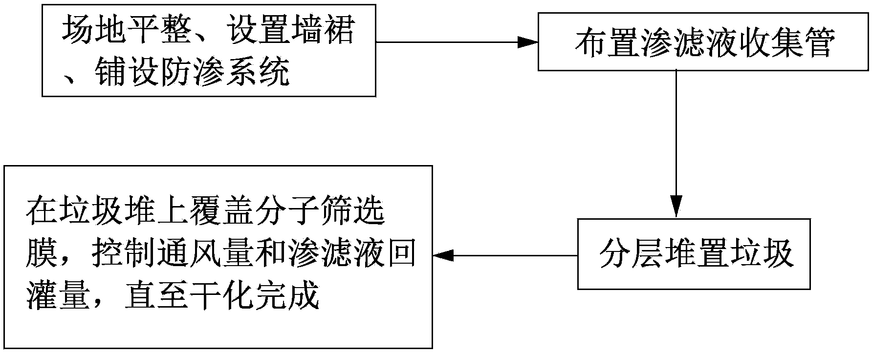
[0037] Waste biological drying treatment in a waste transfer station of a university in Hangzhou City, Zhejiang Province.
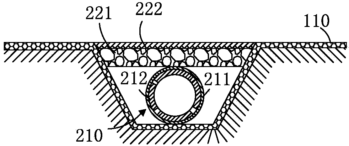
[0038] (1) if figure 2 As shown, simply level and compact the dry site to ensure that the vertical and horizontal slopes are not less than 2%. A leachate collection tank 200 is arranged along the longitudinal axis of the site 100, such as image 3 As shown, the section shape of the leachate collection tank 200 is trapezoidal, with a width of 50 cm at the top, a width of 20 cm at the bottom, and a depth of 30 cm.
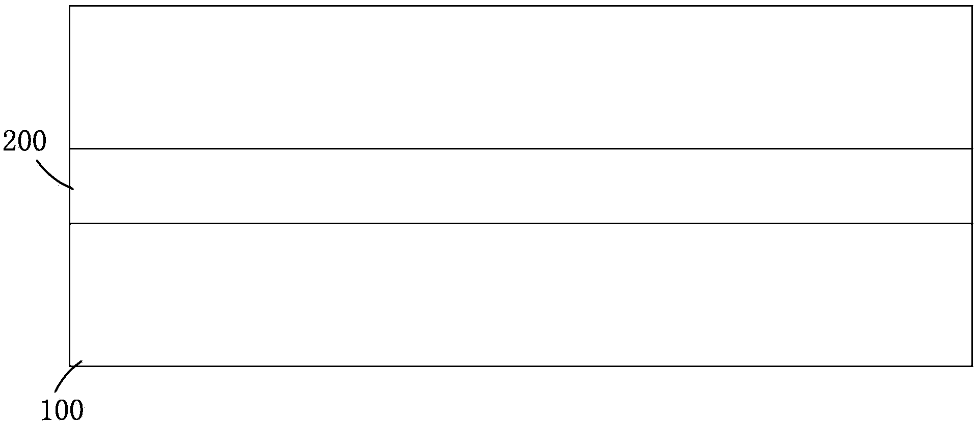
[0039] Lay the anti-seepage layer 110 on the leveled site 100, such as Figure 4 As shown, the anti-seepage layer consists of an 8.0mm thick composite drainage network 111, a 6.0mm thick sodium bentonite liner 112 (GCL), a 2.0mm thick high-density polyethylene geomembrane 113 (HDPE film) stacked sequentially from bottom to top. ) and 10.0mm thick composite drainage net 114, which are respectively used as groundwater diversion layer, under-me...
Embodiment 2
[0055] Bio-drying treatment of garbage in a sanitary landfill in Jinhua City, Zhejiang Province.
[0056] (1) The drying site is selected next to the existing adjustment pool of the landfill site, and the site is simply leveled and compacted to ensure that the vertical and horizontal slopes are not less than 2%. Such as Figure 6 As shown, a leachate collection tank 200 is arranged every 4.0m along the longitudinal direction of the site 100, such as image 3 As shown, the cross-sectional structure of the leachate collection tank 200 is trapezoidal, with a width of 80 cm at the top, a width of 40 cm at the bottom, and a depth of 50 cm.
[0057] Such as Figure 4 As shown, 8.0mm thick composite drainage network, 6.0mm thick sodium bentonite liner (GCL), 2.0mm thick high-density polyethylene geomembrane (HDPE film) and 10.0mm thick composite drainage network were laid in sequence on the leveled site surface , used respectively as groundwater diversion layer, under-membrane pro...
Embodiment 3
[0070] Bio-drying treatment of garbage in a sanitary landfill in Wenzhou City, Zhejiang Province.
[0071] (1) The drying site is selected at the edge of the landfill reservoir area, the natural slope of the site 100 is greater than 5%, and the bottom directly uses the original anti-seepage system of the landfill reservoir area, such as Figure 9 As shown, the anti-seepage layer 120 from bottom to top is 6.0mm thick sodium bentonite liner 121 (GCL), 2.0mm thick high-density polyethylene geomembrane 122 (HDPE film) and 600g / m 2 The long-fiber non-woven geotextile 123 does not need additional arrangement.
[0072] A bio-drying site with a length of 10m and a width of 6m is surrounded by bagged clay, and the bagged soil is enclosed and filled to form a fence 300 with a height of 50cm-70cm, and a 2.0mm thick HDPE film is laid on the inside. The original anti-seepage layer 120 is welded and sealed. The newly laid HDPE film is fixed on the outer corner of the fence 300 with bagged...
PUM
 Abstract
Description
Claims
Application Information