An automatic brick laying trolley for building construction

A construction and automatic technology, applied in construction, building structure, processing of building materials, etc., can solve the problems of workers stained with cement bricks, labor-intensive, inconvenient, etc.

Inactive Publication Date: 2022-06-28
天长市石梁建设工程有限公司
View PDF0 Cites 0 Cited by
  • Summary
  • Abstract
  • Description
  • Claims
  • Application Information

AI Technical Summary

Problems solved by technology

[0004] In order to overcome the disadvantages of manual bricklaying workers with high labor intensity, easy to make the hands of workers stained with cement, and inconvenient when laying bricks at different heights, the technical problem of the present invention is: to provide an easy-to-operate, no-manual Manual laying of brick slabs and automatic bricklaying trolleys for building construction capable of laying bricks at different heights

Method used


Image

  • An automatic brick laying trolley for building construction
  • An automatic brick laying trolley for building construction
  • An automatic brick laying trolley for building construction

Examples


Embodiment 1

[0032] An automatic brick laying trolley for building construction, such as figure 1 , figure 2 and image 3 As shown, it includes a base 1 , a moving mechanism 2 and a brick transporting mechanism 3 , a moving mechanism 2 is arranged between the bases 1 , and a brick transporting mechanism 3 is arranged on the moving mechanism 2 .

[0033] When people need to use the device, they first place the device above the wall to be laid with bricks, and then they can place the cement-coated bricks on the brick transporting mechanism 3, and then start the moving mechanism 2 to operate. The moving mechanism 2 operates intermittently, and the moving mechanism 2 will drive the brick conveying mechanism 3 to operate intermittently, so that the brick conveying mechanism 3 drives the brick plate to move to the left intermittently, so that when the cemented brick plate falls from the left side of the moving mechanism 2 to the wall After being installed, the moving mechanism 2 will move to th...

Embodiment 2

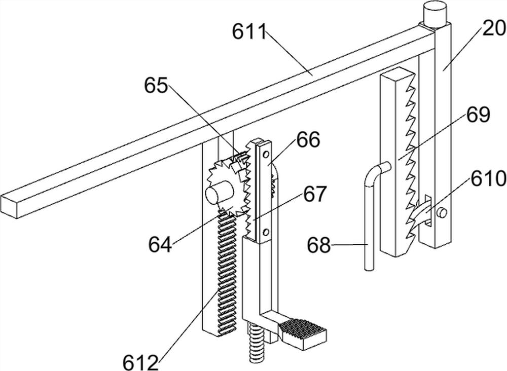
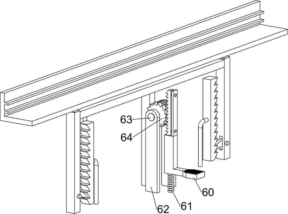
[0038] On the basis of Example 1, as figure 1 , Figure 4 , Figure 5 , Image 6 , Figure 7 , Figure 8 , Figure 9 and Figure 10 As shown, it also includes a material spreading mechanism 4. The material spreading mechanism 4 includes a support rod 40, a material box 41, a third bearing seat 42, a fifth rotating shaft 43, a first gear 44, a second support column 45, and a second slide rail. 46. ​​Baffle plate 47, guide rod 48, first spring 49, top block 410, first fixed block 411, sliding rod 412, second spring 413, wedge block 414, first support block 415, arc slide rail 416 , the slider 417, the third spring 418 and the second bevel gear 419, a support rod 40 is symmetrically provided on the left side of the top of the mounting plate 21, a material box 41 is provided between the support rods 40, and the top left side of the mounting plate 21 is symmetrically provided with a third A fifth rotating shaft 43 is arranged between the bearing seat 42 and the third bearing...


PUM


Abstract

The invention relates to a brick-laying trolley, in particular to an automatic brick-laying trolley for building construction. The invention provides an automatic brick-laying trolley for building construction, which is easy to operate, does not need manual laying of brick slabs and can lay bricks at different heights. An automatic brick-laying trolley for building construction, comprising: a base, a moving mechanism is arranged between the bases; a brick transporting mechanism, and a brick transporting mechanism is arranged on the moving mechanism. The present invention realizes the intermittent laying and intermittent transmission of the brick slabs through the brick transport mechanism, and then realizes the continuous rightward laying of the brick slabs with the cooperation of the moving mechanism; the laying of the cement is realized by providing a paving mechanism, and then With the cooperation of the brick transporting mechanism, the brick slabs are transferred to the paving mechanism, and the paving mechanism operates to make the brick slabs fall onto the cement stably, so that bricklaying can be carried out better.

Description

technical field [0001] The invention relates to a brick-laying trolley, in particular to an automatic brick-laying trolley for building construction. Background technique [0002] When people need to build different buildings, they need workers to lay bricks. People first lay a layer of cement where the bricks need to be laid, then place the bricks on the cement, and then use tools to carry out the brickwork. The percussion makes the bricks and the cement more closely attached, so the labor intensity of the workers who operate for such a long time is high, and because the bricks are taken and the cement is laid manually, it is easy to make the workers' hands stained with cement. In addition, when laying bricks in lower places, it is necessary to bend down manually, and for higher places, it is necessary to lay with tools, which is more inconvenient. [0003] Therefore, in view of the above shortcomings, we need to develop an automatic brick laying trolley for building const...

Claims


Application Information

Patent Timeline
Patent Type & Authority Patents(China)
IPC IPC(8): E04G21/22
CPCE04G21/22
Inventor 肖强
Owner 天长市石梁建设工程有限公司
Why Eureka
Try Eureka