High-voltage power cable laying device

A high-voltage cable and wiring device technology, which is applied in cable laying equipment, transportation and packaging, and thin material processing, etc., can solve the problems of unsatisfactory cable multi-line laying and backward laying devices

Active Publication Date: 2021-03-19
国网山东省电力公司曲阜市供电公司 +2
View PDF8 Cites 0 Cited by
  • Summary
  • Abstract
  • Description
  • Claims
  • Application Information

AI Technical Summary

Problems solved by technology

[0005] However, the devices disclosed in the prior art can only lay and install a single roll of cable coil material, resulting in that the cable coil material cannot meet the multi-line laying of cables during the laying and installation process. Specifically, during the cable erection process, there are often multiple Parallel cables are laid and erected at the same time. Obviously, the laying devices disclosed in the prior art are backward, and it is impossible to conveniently and effectively lay and erect cables

Method used


Image

  • High-voltage power cable laying device
  • High-voltage power cable laying device
  • High-voltage power cable laying device

Examples


Embodiment 1

[0043] Example 1 Power high voltage cable wiring device

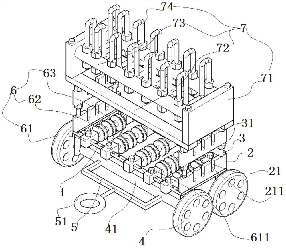
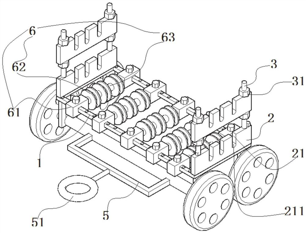
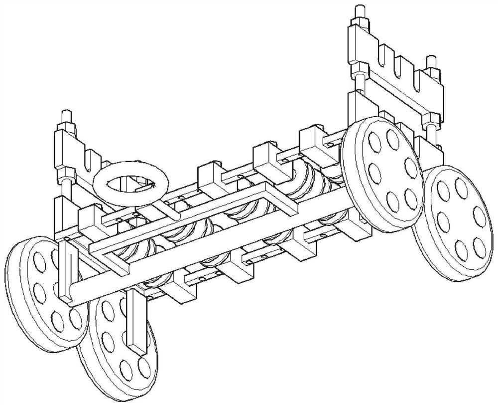
[0044] Such as Figure 1-7 As shown, a power high voltage cable wiring device includes a rectangular unit rod 1; a rectangular machine lever 1 slides to connect a plurality of left and right intervals set up a cable shaping member 6;

[0045] The cable discharge member 6 includes a sliding connection to a rectangular machine lever 1, a bearing mount 61 on the rear sides, and the bearing mount 61 is rotated between the connecting shaft 63 (the bearing mount 61 is fitted) The bearing, the arranging shaft 63 is rotated in the bearing), and a plurality of front and rear spacer disposed on the bearing shaft 63 are fixed; the discharge wheel 62 is opened on the platen 621;

[0046] The bearing mount 61 is threaded and connected to the positioning bolt 611, and the rectangular machine rod 1 is opened on the rectangular housing rod 1.

[0047] The left and right ends of the rectangular machine holder 1 are fixedly connected to the w...

Embodiment 2

[0067] Example 2 laying method

[0068] Such as Figure 1-7 As shown, the present embodiment is based on the apparatus structure disclosed in Example 1, and the laying method of the power high voltage cable wiring device is disclosed. Specifically, the specific structure of the power high voltage cable wiring apparatus is as follows:

[0069] A power high voltage cable wiring device includes a rectangular machine lever 1; a rectangular machine frame rod 1 slides to connect a plurality of left and right intervals set up a cable shaping member 6;

[0070] The cable discharge member 6 includes a sliding connection to a rectangular machine lever 1, a bearing mount 61 on the rear sides, and the bearing mount 61 is rotated between the connecting shaft 63 (the bearing mount 61 is fitted) The bearing, the arranging shaft 63 is rotated in the bearing), and a plurality of front and rear spacer disposed on the bearing shaft 63 are fixed; the discharge wheel 62 is opened on the platen 621;

[...


PUM


Abstract

The invention discloses a high-voltage power cable laying device. The high-voltage power cable laying device comprises a rectangular frame rod, wherein a plurality of cable unwinding parts arranged atintervals on the left side and the right side are connected to the rectangular frame rod in a sliding mode; each cable unwinding part comprises bearing mounting seats which are connected to the frontside and the rear side of the rectangular frame rod in a sliding mode; an unwinding shaft is rotatably connected between the bearing mounting seats; each unwinding shaft is fixedly connected with a plurality of unwinding wheels which are arranged at intervals in a direction from front to back; a winding groove is formed in each unwinding wheel; cable guide grid plate parts are fixedly connected to the left end and the right end of the rectangular frame rod; each cable guide grid plate part comprises two cable guide grid plates which are arranged at intervals at the upper part and the lower part; each cable guide grid plate is provided with a plurality of cable guide openings matched with the corresponding winding grooves; and two height adjusting parts which are arranged at intervals in adirection from front to back are used for adjusting the height between the cable guide grid plates. Through adoption of the part design of the device, the laying and mounting efficiency of the cablesis effectively improved.

Description

Technical field [0001] The present invention relates to the field of high voltage cable devices, and more particularly to a power high voltage cable wiring device. Background technique [0002] The high voltage cable is one of the power cable refers to a power cable for transmitting 1kV-1000kV, which is used in power transmission and distribution. Components from the inside throughput include: conductors, insulation, internal care, filler (armored), and external insulation. Of course, the armored high-voltage cable is mainly used to be buried, which can resist high-strength oppression on the ground while preventing other external force damage. [0003] With the development of my country's electricity, high-voltage cables have gradually spread, so the laving density of high voltage cables and the range of layouts are gradually increased. [0004] During the laving process of the high voltage cable, it is often necessary to make a regular installation installation of the contained ...

Claims


Application Information

Patent Timeline
Patent Type & Authority Applications(China)
IPC IPC(8): B65H49/24B65H49/26B65H49/32B65H49/36B65H57/04B65H67/06H02G1/06
CPCB65H49/26B65H49/324B65H49/24B65H49/36B65H57/04B65H67/069H02G1/06B65H2701/34
Inventor 陈强刘康孔琳琳孔宁储学法苏纯宝张贵洋许帆屈强颜廷国孙钊张亚南
Owner 国网山东省电力公司曲阜市供电公司
Why Eureka
Try Eureka