PV valve for ballast tank

A technology of ballast tanks and pressure valves, applied in valve details, safety valves, balance valves, etc., can solve problems such as inconvenient discharge, and achieve tight fit and good effect

Pending Publication Date: 2021-03-23
JIANGSU NANJI MACHINERY
View PDF0 Cites 6 Cited by
  • Summary
  • Abstract
  • Description
  • Claims
  • Application Information

AI Technical Summary

Problems solved by technology

[0004] Aiming at the deficiencies of the prior art, the present invention provides a PV valve used in ballast tanks, which can conveniently complete the pressure relief when the pressure in the ballast tank is too high and needs to be released outwards, and at the same time can be used in ballast tanks. When the air pressure in the tank is too low, it is more convenient to pressurize the ballast tank inwardly, and it can prevent water from entering the ballast tank when the water pressure in the ballast tank is too high, which solves the problem of the vacuum in the ballast tank. The problem of inconvenient discharge when the pressure needs to be released

Method used


Image

  • PV valve for ballast tank
  • PV valve for ballast tank
  • PV valve for ballast tank

Examples


Embodiment Construction

[0025] The following will clearly and completely describe the technical solutions in the embodiments of the present invention with reference to the accompanying drawings in the embodiments of the present invention. Obviously, the described embodiments are only some, not all, embodiments of the present invention. Based on the embodiments of the present invention, all other embodiments obtained by persons of ordinary skill in the art without making creative efforts belong to the protection scope of the present invention.

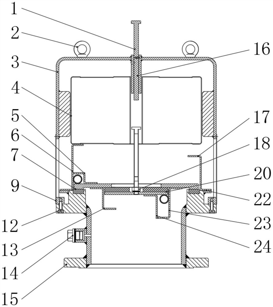
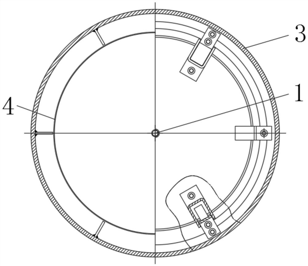
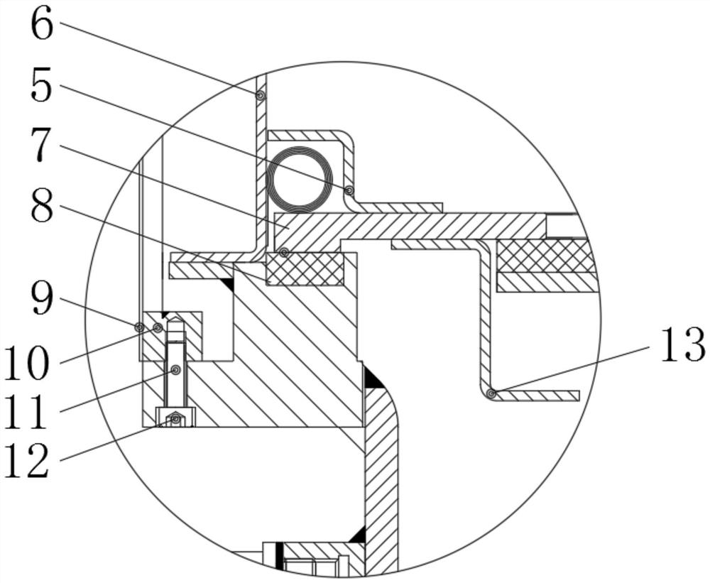
[0026] see Figure 1-4 , a PV valve for a ballast tank, comprising a vacuum pressure relief rod 1, an eyebolt 2 is arranged on the outside of the vacuum pressure relief rod 1, a casing 3 is arranged at the lower end of the eyebolt 2, and the inside of the casing 3 A float 4 is provided, the lower end of the float 4 is provided with a pressure valve disc guide seat 5, a pressure spring 6 is provided between the pressure valve disc guide seat 5 and the float 4, ...


PUM


Abstract

The invention relates to the technical field of PV valves, and discloses a PV valve for a ballast tank. The PV valve for the ballast tank comprises a vacuum pressure relief rod, a lifting bolt is arranged on the outer side of the vacuum pressure relief rod, a shell is arranged at the lower end of the lifting bolt, a floater is arranged inside the shell, a pressure valve disc guide seat is arrangedat the lower end of the floater, a pressure spring is arranged between the pressure valve disc guide seat and the floater, and a pressure valve disc body is arranged at the lower end of the pressurevalve disc guide seat. The PV valve for the ballast tank has the advantages that pressure relief can be conveniently completed when the air pressure in the ballast tank is too high and needs to be released outwards, meanwhile, pressurization in the ballast tank can be conveniently completed when the air pressure in the ballast tank is too low and needs to be increased inwards, water can be prevented from entering the ballast tank when the water pressure in the ballast tank is too high, the problem that when vacuum pressure in the ballast tank needs to be discharged, discharging is inconvenientis solved, and a better using prospect can be brought.

Description

technical field [0001] The invention relates to the technical field of PV valves, in particular to a PV valve used in ballast tanks. Background technique [0002] The PV valve used for ballast tank is a kind of PV valve used for ballast tank; the existing PV valve used for ballast tank has certain disadvantages in use, and the PV valve used for ballast tank first It is not possible to conveniently complete the pressure relief when the pressure in the ballast tank is too high and needs to release the pressure outward. Secondly, it is not possible to complete the pressure relief in the ballast tank when the pressure in the ballast tank is too low and needs to be pressurized inward. In addition, when the water pressure in the ballast tank is too high, it cannot prevent water from entering the ballast tank, which is not practical enough. Finally, when the vacuum pressure in the ballast tank needs to be discharged, it cannot be easily discharged. For this reason, we A PV valve f...

Claims


Application Information

Patent Timeline
Patent Type & Authority Applications(China)
IPC IPC(8): F16K17/196F16K17/19F16K27/02F16K31/60B63J4/00
CPCB63J4/002F16K17/19F16K17/196F16K27/02F16K31/60
Inventor 倪建峰王建海吉向荣刘燕郭晓东周圣庆徐志
Owner JIANGSU NANJI MACHINERY
Why Eureka
Try Eureka