Pressure-limiting valve device and pressure cooker

A pressure-limiting valve and valve body technology, applied in the field of kitchen appliances, can solve problems such as easy burns to users, and achieve the effect of increasing safe working pressure

Pending Publication Date: 2019-11-19
GREE ELECTRIC APPLIANCES INC
View PDF0 Cites 4 Cited by
  • Summary
  • Abstract
  • Description
  • Claims
  • Application Information

AI Technical Summary

Problems solved by technology

[0004] Therefore, the technical problem to be solved by the present invention is to overcome the defect that the pressure limiting valve device in the prior art is easy to burn the user when exhausting, thereby providing a pressure limiting valve device and a pressure cooker that are not easy to burn the user when exhausting.

Method used


Image

  • Pressure-limiting valve device and pressure cooker
  • Pressure-limiting valve device and pressure cooker
  • Pressure-limiting valve device and pressure cooker

Examples


Embodiment 1

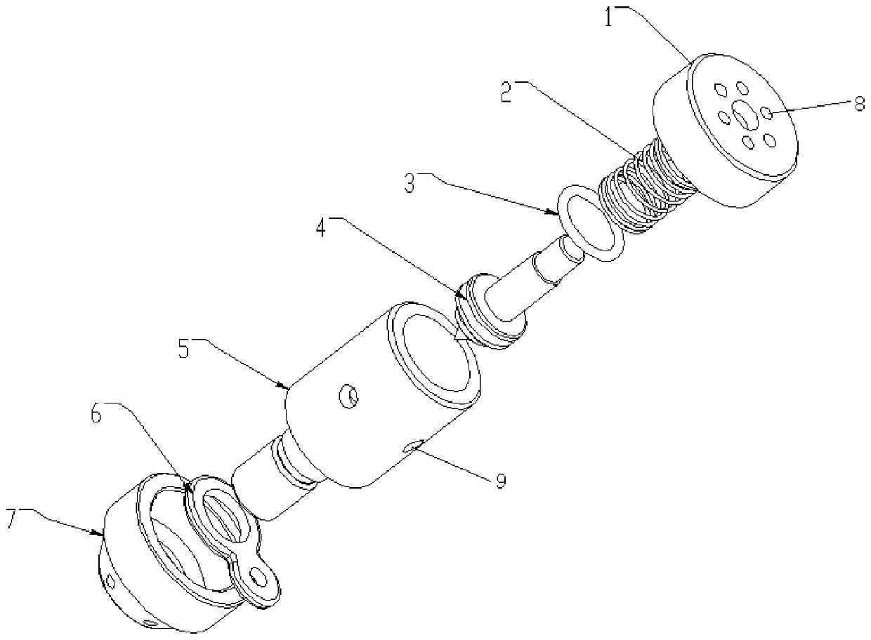
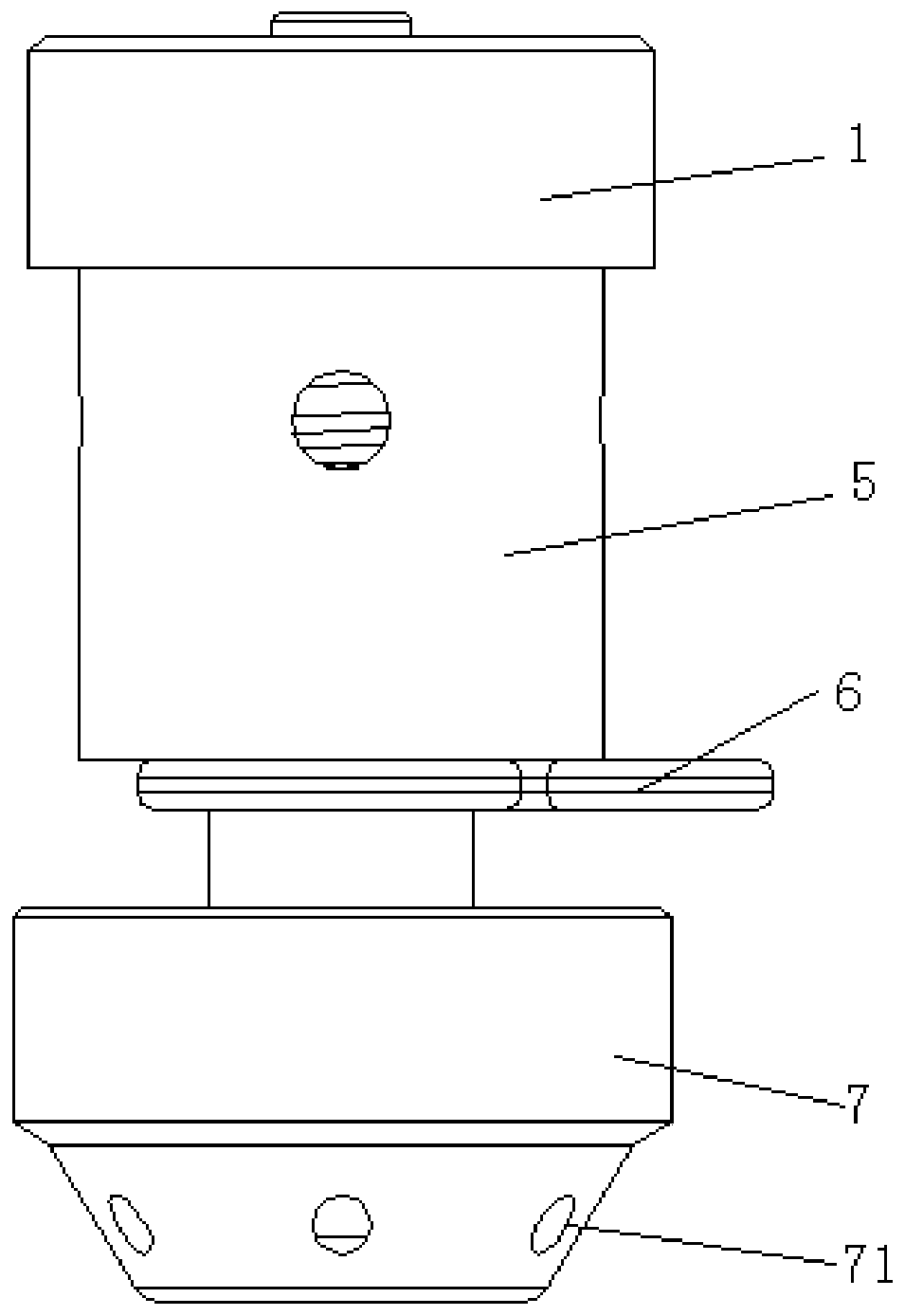
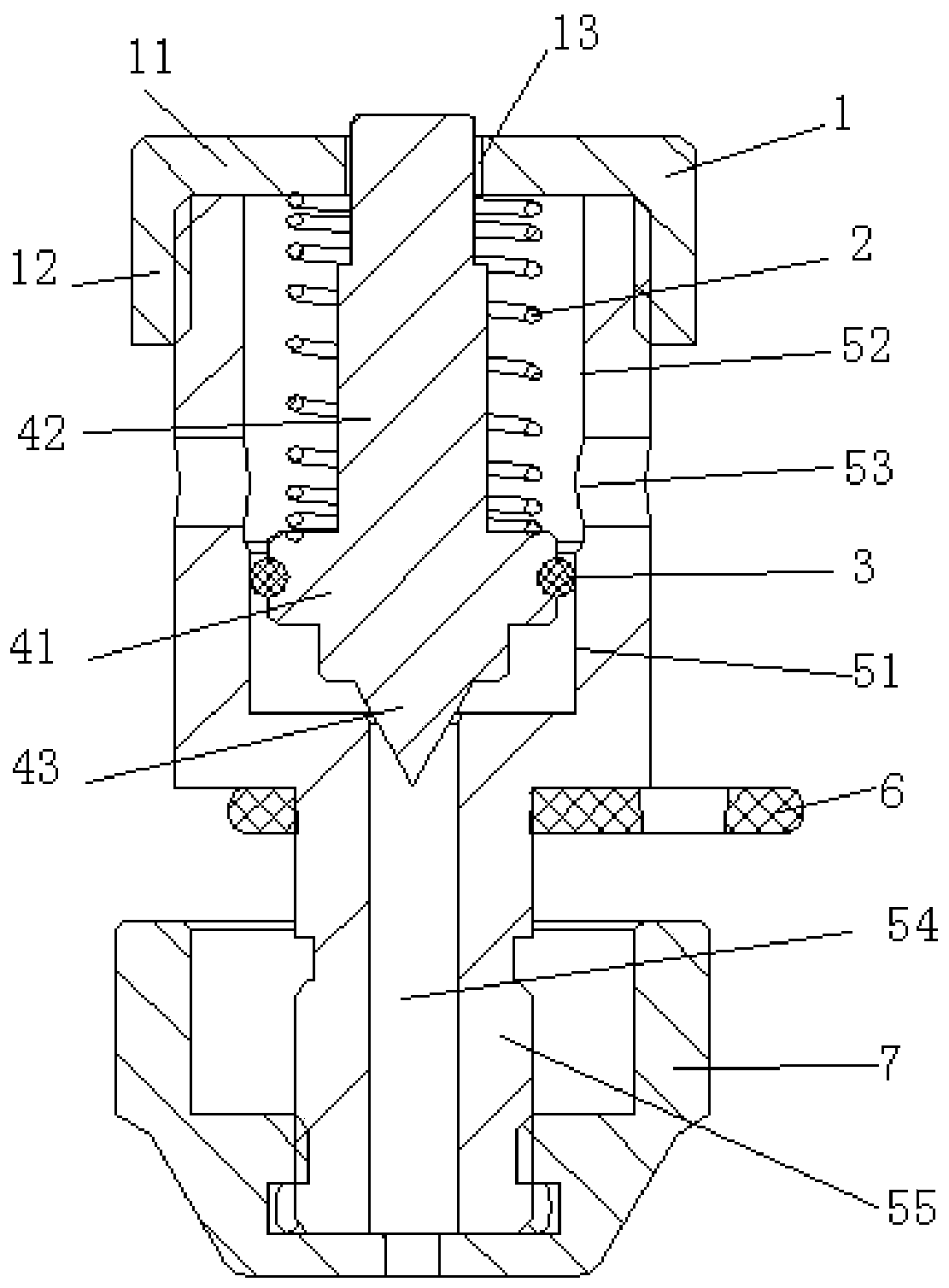
[0057] This embodiment provides a specific implementation of the pressure limiting valve device, such as Figure 1 to Figure 5 As shown, it includes a valve body and a piston assembly inside the valve body.

[0058] Wherein the inside of the valve body is provided with a first passage 54 suitable for communicating with the interior of the pot body, and a cavity communicated with the first passage 54, and the valve body is provided with a second passage 8 communicated with the cavity. , the outlet of the second passage 8 is arranged on the top surface of the valve body, and faces upward; the piston assembly is movably arranged in the cavity, and has the function of connecting the first passage 54 with the second A first position in which the channel 8 communicates, and a second position in which the first channel 54 is disconnected from the second channel 8 . Wherein the second channel 8 is a plurality of through holes processed on the top surface of the valve body.

[0059] ...

Embodiment 2

[0078] This embodiment provides a pressure cooker, including the pressure limiting valve device provided in the above embodiments, and the pressure cooker is not easy to burn the user when exhausting air.


PUM


Abstract

The invention provides a pressure-limiting valve device and a pressure cooker; the pressure-limiting valve device comprises a valve body and a position assembly, wherein a first channel suitable for being communicated with the inner part of the pot body and a cavity communicated with the first channel are formed in the valve body; a second channel communicated with the cavity is formed in the valve body, and the outlet of the second channel is formed in the top surface of the valve body and faces upwards; the piston assembly is movably arranged in the cavity and has a first position enabling the first channel to be communicated with the second channel, and a second position enabling the first channel to be disconnected from the second channel; the piston assembly is arranged in the valve body and cannot be removed from the valve body; and due to the fact that the outlet of the second channel faces upwards, air cannot blow to a person, so that a user is not scalded easily.

Description

technical field [0001] The invention relates to the technical field of kitchen utensils, in particular to a pressure limiting valve device and a pressure cooker. Background technique [0002] A spring-type multifunctional pressure-limiting valve is disclosed in the prior art, including a pressure-limiting valve body, a valve core, a nut, a spring, a sealing ring, and a nut. It is characterized in that the middle of the pressure-limiting valve body is a cylindrical hole, and its circumference The surface is provided with a pressure-holding hole, a lower vent hole, a first-stage vent hole, and a second-stage vent hole. The valve core is a cylindrical shaft, which is placed in the pressure-limiting valve body through a spring, and the upper end of the valve core is screwed together with the nut. On the body of the pressure limiting valve, there is a groove on the side of the cylinder at the lower end of the valve core, the nut is screwed and connected with the lower end of the ...

Claims


Application Information

Patent Timeline
Patent Type & Authority Applications(China)
IPC IPC(8): A47J27/09A47J27/08A47J36/38
CPCA47J27/08A47J27/09A47J36/38
Inventor 成灿明黄伟崇金长国刘格珠
Owner GREE ELECTRIC APPLIANCES INC
Why Eureka
Try Eureka