Spatial curved surface intersection method executed by electronic equipment and electronic equipment

A surface intersection and electronic equipment technology, applied in the computer field, can solve problems such as limited computational scale, increased hardware costs, computer memory overflow, etc., to achieve the effects of ensuring existence and uniqueness, improving computing speed, and solving memory overflow

Pending Publication Date: 2021-03-23
ACAD OF MATHEMATICS & SYSTEMS SCIENCE - CHINESE ACAD OF SCI
View PDF0 Cites 0 Cited by
  • Summary
  • Abstract
  • Description
  • Claims
  • Application Information

AI Technical Summary

Problems solved by technology

[0002] Among the existing methods of intersecting between implicit surfaces in the surface intersecting problem of two geometric bodies in computer-aided design, the grid method of the symbolic calculation method and the numerical method are commonly used at present; the symbolic method (mainly refers to Triangular column method, Groebner basis method, knot method, etc.), mainly for solving polynomial systems, its computable scale is very limited, and the accumulation of coefficients in the calculation process of a larger function system may easily lead to computer memory overflow, and the computer’s processor In the process of solving, the processing speed is very slow, and the intersection line of the geometry may not even be obtained. For a relatively small function system, even if it can be calculated, the requirements for computer memory and hardware are very high, which greatly increases the hardware cost.
[0003] The grid method, segmentation method and tracking method of the numerical method are more efficient than the symbolic method in terms of calculation time, but it cannot guarantee that the obtained intersection line is topology-preserving, and there are many points or missing points, and the calculation result cannot be guaranteed to be in the theoretical credibility

Method used


Image

  • Spatial curved surface intersection method executed by electronic equipment and electronic equipment
  • Spatial curved surface intersection method executed by electronic equipment and electronic equipment
  • Spatial curved surface intersection method executed by electronic equipment and electronic equipment

Examples


Embodiment Construction

[0034] Hereinafter, embodiments of the present disclosure will be described with reference to the drawings. It should be understood, however, that these descriptions are exemplary only, and are not intended to limit the scope of the present disclosure. In the following detailed description, for purposes of explanation, numerous specific details are set forth in order to provide a thorough understanding of the embodiments of the present disclosure. It may be evident, however, that one or more embodiments may be practiced without these specific details. Also, in the following description, descriptions of well-known structures and techniques are omitted to avoid unnecessarily obscuring the concepts of the present disclosure.

[0035] The terminology used herein is for the purpose of describing particular embodiments only, and is not intended to be limiting of the present disclosure. The terms "comprising", "comprising", etc. used herein indicate the presence of stated features,...


PUM


Abstract

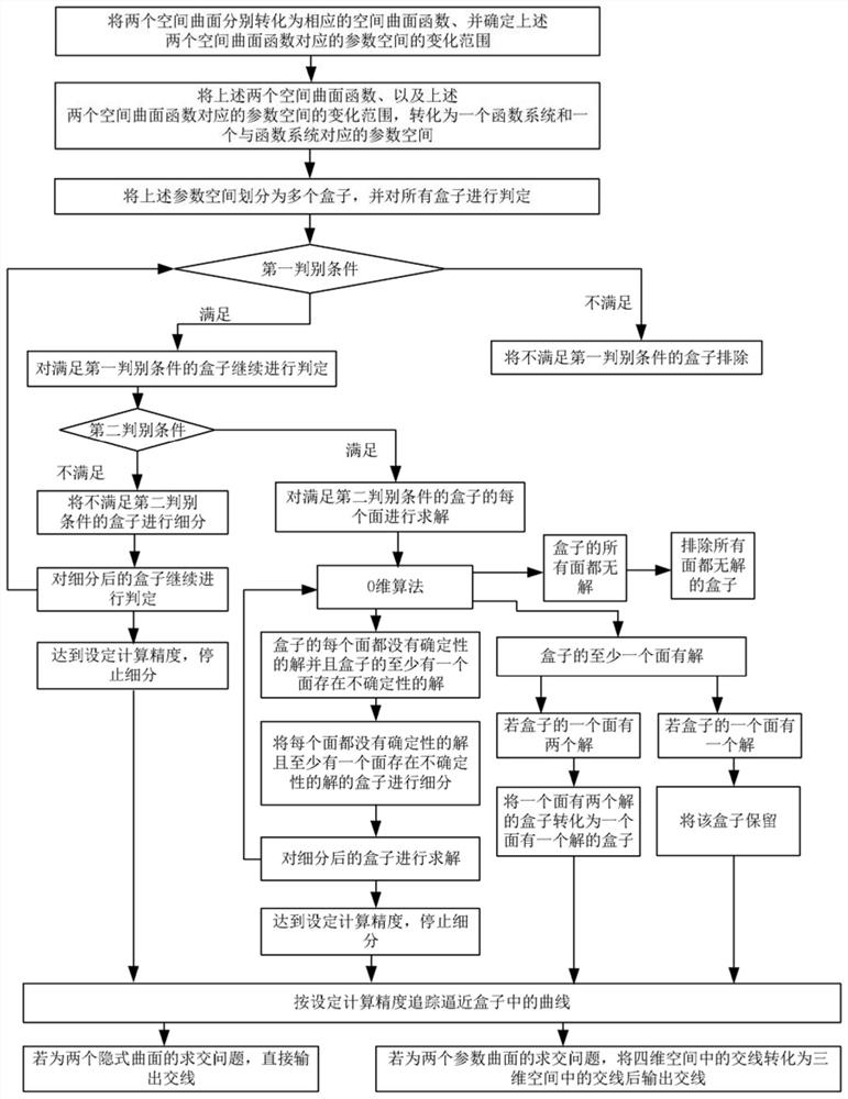
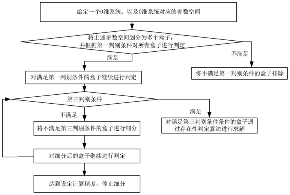
The invention provides a spatial curved surface intersection method executed by electronic equipment and the electronic equipment. The spatial curved surface intersection method comprises the following steps: finally converting two spatial curved surfaces into a function system and a parameter space corresponding to the function system; dividing the parameter space into a plurality of boxes; judging all the boxes according to a first judgment condition, filtering out the boxes which do not meet the first judgment condition, and judging the boxes which meet the first judgment condition according to a second judgment condition; and solving each surface of the box which meets the first discrimination condition and the second discrimination condition before subdivision and each surface of thebox which meets the first discrimination condition and the second discrimination condition after subdivision through a zero-dimensional algorithm, and tracking the curve in the approximation box for the box which meets the requirements after solving according to the set calculation precision, and outputting an intersection line as required.

Description

technical field [0001] The present disclosure relates to the field of computer technology, and more specifically, to a method for intersecting space curved surfaces executed by electronic equipment and the electronic equipment. Background technique [0002] Among the existing methods of intersecting between implicit surfaces in the surface intersecting problem of two geometric bodies in computer-aided design, the grid method with symbolic calculation method and numerical method is more commonly used at present; the symbolic method (mainly refers to Triangular column method, Groebner basis method, knot method, etc.), mainly for solving polynomial systems, its computable scale is very limited, and the accumulation of coefficients in the calculation process of a larger function system may easily lead to computer memory overflow, and the computer’s processor In the process of solving, the processing speed is very slow, and it may not even be possible to obtain the intersection l...

Claims


Application Information

Patent Timeline
IPC IPC(8): G06F17/15G06F17/16
CPCG06F17/15G06F17/16
Inventor 程进三文钧屹
Owner ACAD OF MATHEMATICS & SYSTEMS SCIENCE - CHINESE ACAD OF SCI
Why Eureka
Try Eureka