Flash storage error detection method and circuit, storage medium and terminal

A technology for storing errors and circuits, which is applied in the field of flash detection, can solve problems such as slow operation efficiency, and achieve the effects of improving yield rate, reducing production cost, and improving detection efficiency

Pending Publication Date: 2021-03-23
XTX TECH INC
View PDF0 Cites 2 Cited by
  • Summary
  • Abstract
  • Description
  • Claims
  • Application Information

AI Technical Summary

Problems solved by technology

[0005] The purpose of the present invention is to provide a method, circuit, storage medium and terminal for detecting errors in flash storage, aiming to solve the problem that the existing flash needs to

Method used


Image

  • Flash storage error detection method and circuit, storage medium and terminal
  • Flash storage error detection method and circuit, storage medium and terminal
  • Flash storage error detection method and circuit, storage medium and terminal

Examples


Example Embodiment

[0032]Next, the technical solutions in the present application will be described in conjunction with the present application embodiments, and it is clear that the described embodiments are intended to be described herein, not all of the embodiments of the present application. Components of the present application embodiments described and illustrated in the drawings herein can be arranged and designed in a variety of different configurations. Thus, the detailed description of the embodiments of the present application provided in the drawings is not intended to limit the scope of the present application claimed, but only the selected embodiments of the present application. Based on the embodiments of the present application, those skilled in the art will belong to the scope of the present application without the premise of creative labor.

[0033]It should be noted that similar reference numerals and letters represent the like items in the drawings below, and therefore, once one is def...


PUM


Abstract

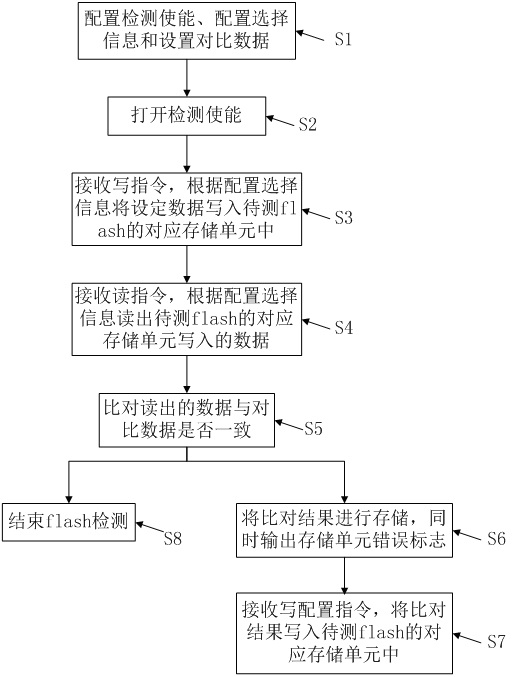
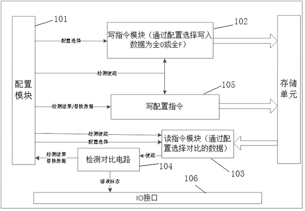
The invention discloses a flash storage error detection method and circuit, a storage medium and a terminal, a special configuration signal is adopted in a CP test mode, a flash to be tested can use anormal write instruction to write fixed data in the test mode, data is read and compared at the same time through a read instruction in the test mode, and a mark signal of a comparison result is output. Meanwhile, wrong addresses are stored, and a damaged area can be replaced with a redundant storage area when the flash to be tested is powered on next time, the whole flash to be tested does not need to be written in and then read out, the storage area which cannot be erased in the chip can be determined while testing is conducted, the detection efficiency of flash storage errors is greatly improved, and redundancy replacement is achieved, by adopting the scheme, the flash yield can be effectively improved, the production cost is reduced, and the chip which cannot be erased and the storagearea which cannot be erased in the chip can be quickly detected in the CP test stage.

Description

technical field [0001] The invention relates to the technical field of flash detection, in particular to a method, circuit, storage medium and terminal for detecting errors in flash storage. Background technique [0002] Because the domestic flash technology is not perfect, when the flash leaves the factory, there is a certain probability that some storage area circuits of the flash cannot be erased successfully. In order to improve the yield and reliability of the flash, the redundant storage area (redundance ) to replace the area that cannot be erased successfully. [0003] But before the replacement, it is necessary to detect the location of the area that cannot be erased by the flash. The traditional method is to erase the entire flash, and then read the data of the entire flash, and then compare the data to determine the address of the wrong data, and then Know the location of the area that cannot be erased by the flash, and then use the redundant storage area (redunda...

Claims


Application Information

Patent Timeline
IPC IPC(8): G11C29/00G11C29/44
CPCG11C29/006G11C29/4401
Inventor 刘佳庆黎永健蒋双泉
Owner XTX TECH INC
Why Eureka
Try Eureka