Tab limiting plate, battery module, battery pack and automobile
A battery module and limit plate technology, which is applied to battery components, circuits, electrical components, etc., can solve problems such as long welding time, reduced power battery production efficiency, and cumbersome operations
- Summary
- Abstract
- Description
- Claims
- Application Information
AI Technical Summary
Problems solved by technology
Method used
Image
Examples
Embodiment 1
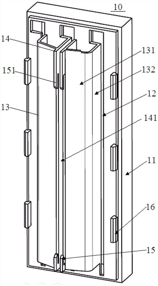
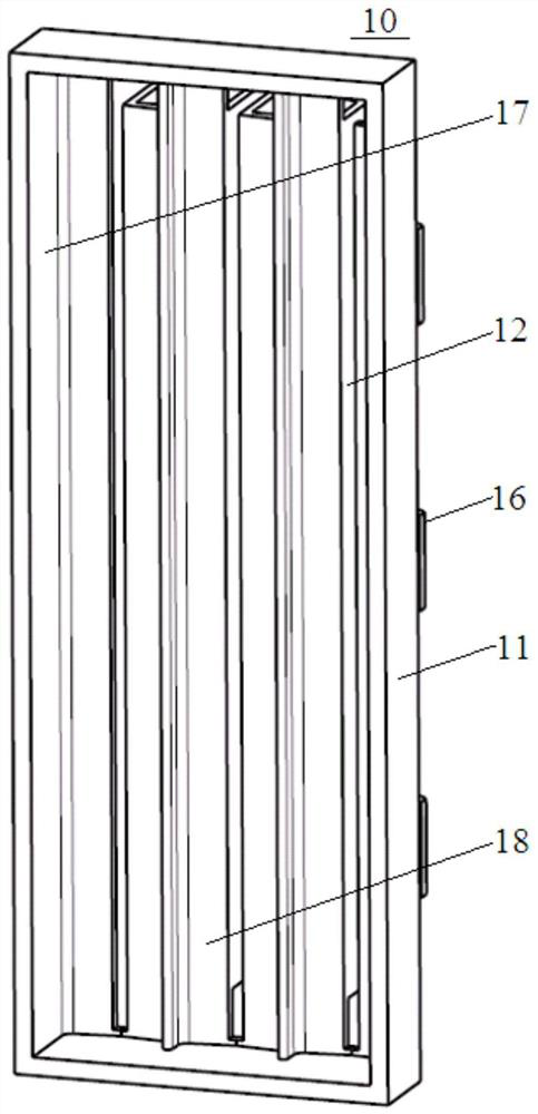
[0044] A kind of pole lug limiting plate 10, its structure is as figure 1 and figure 2 As shown, the main body includes a base 11, and the base 11 is provided with more than two tab passing holes 12 parallel to each other and tab guiding surfaces 13 having the same number as the tab passing holes 12, and the tab guiding surfaces 13 The positions are in one-to-one correspondence with the positions where the tabs pass through the holes 12 .
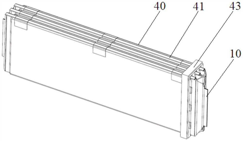
[0045] The base 11 is the main body of the lug limiting plate 10 , and the tab limiting plate 10 is sleeved on the end of the soft pack cell assembly 40 through the base 11 . Specifically, see figure 2 and Figure 5 , in this embodiment, a tab isolation cavity 17 is provided on the back of the base 11 for accommodating the end of the soft-pack battery assembly 40, and the base 11 is set in the soft-pack battery through the tab isolation cavity 17. The end of the core assembly 40 . An end limit surface 18 is provided inside the lug is...
Embodiment 2
[0063] Based on the same inventive concept, this embodiment provides a battery module 100, the structure of which is as follows Figure 6 As shown, it includes a set of flat and long battery module 130, wire harness isolation plate and bus bar assembly 120 and module housing 110, the wire harness isolation plate and bus bar assembly 120 are installed at both ends of the flat and long battery module 130, and the wire harness The isolation plate and bus bar assembly 120 specifically includes a wire harness isolation plate 121 and a bus bar 122. The wire harness isolation plate 121 and the bus bar 122 can be set in an integrated structure or a split structure. In this embodiment, the wire harness isolation plate and the bus bar assembly 120 For the detailed structure, reference may be made to the prior art, and the present invention is not specifically limited. The wire harness isolation plate and bus bar assembly 120 and a set of flat and long cell modules 130 are all covered in...
Embodiment 3
[0069] Based on the same inventive concept, this embodiment provides another battery module 100, the structure of which is as follows Figure 7 As shown, it includes more than 2 sets of flat and long battery modules 130, wire harness isolation plates, busbar assemblies 120 and module casings 110, and more than 2 sets of flat and long battery modules 130 are stacked along the thickness direction of the soft-packed batteries to form a In the cell stack 140, a flame retardant and high temperature resistant pad can be arranged between two adjacent groups of elongated cell modules 130. The wire harness isolation plate and bus bar assembly 120 is installed at both ends of the cell stack 140. The wire harness isolation plate and bus bar assembly 120 specifically includes a wire harness isolation plate 121 and a bus bar 122. The wire harness isolation plate 121 and the bus bar 122 can be set as one structure or split structure, the detailed structure of the wire harness isolation plat...
PUM
| Property | Measurement | Unit |
|---|---|---|
| length | aaaaa | aaaaa |
Abstract
Description
Claims
Application Information
 - R&D
- Intellectual Property
- Life Sciences
- Materials
- Tech Scout
- Unparalleled Data Quality
- Higher Quality Content
- 60% Fewer Hallucinations
Browse by: Latest US Patents, China's latest patents, Technical Efficacy Thesaurus, Application Domain, Technology Topic, Popular Technical Reports.
© 2025 PatSnap. All rights reserved.Legal|Privacy policy|Modern Slavery Act Transparency Statement|Sitemap|About US| Contact US: help@patsnap.com


