Video transmission equipment for Internet communication

A technology for Internet communication and video transmission, which is applied in the field of video transmission equipment for Internet communication, which can solve the problems of large internal equipment load, inconvenient replacement, inflexible and convenient operation, etc., and achieve the effect of improving functionality and stability

Pending Publication Date: 2021-03-23
苏州北华科创服务有限公司
View PDF0 Cites 0 Cited by
  • Summary
  • Abstract
  • Description
  • Claims
  • Application Information

AI Technical Summary

Problems solved by technology

[0005] Aiming at the deficiencies of the prior art, the present invention provides a video transmission device for Internet communication, which is equipped with a combination of metal filter and multiple sets of heat sinks, direct external heat dissipation, and is convenient for disassembly and assembly, and other functions can be added according to requirements Enhanced components, improved functionality, and at the same time, through the touch screen operation, it has the advantages of playing, which can be connected externally and used directly, which solves the problem of traditional long-term use, large internal equipment load, high temperature, and poor heat dissipation And the residual temperature cannot be handled, which affects the long-term use of the equipment. Secondly, there are multiple sets of supporting products, the internal structure is inconvenient to replace, and the installation and maintenance are troublesome. Insufficient operation, insufficient flexibility and convenience

Method used


Image

  • Video transmission equipment for Internet communication
  • Video transmission equipment for Internet communication
  • Video transmission equipment for Internet communication

Examples


Embodiment Construction

[0027] The following will clearly and completely describe the technical solutions in the embodiments of the present invention with reference to the accompanying drawings in the embodiments of the present invention. Obviously, the described embodiments are only some, not all, embodiments of the present invention. Based on the embodiments of the present invention, all other embodiments obtained by persons of ordinary skill in the art without making creative efforts belong to the protection scope of the present invention.

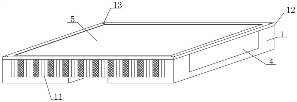
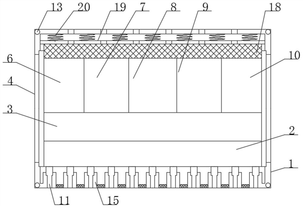
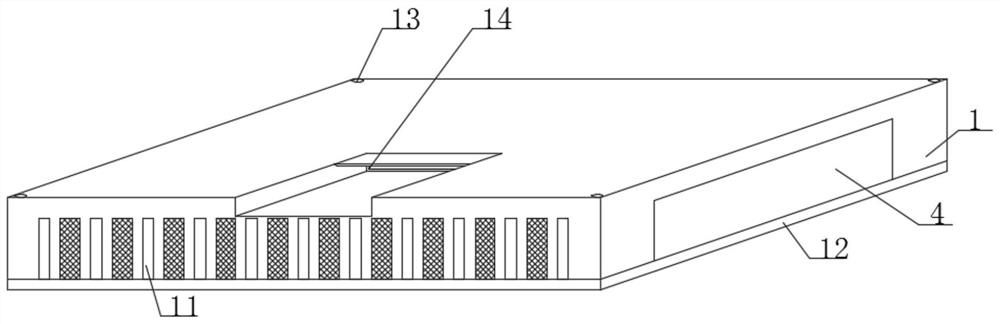
[0028] see Figure 1-6 , a video transmission device for Internet communication, comprising a device casing 1, a storage battery 2 is arranged inside the device casing 1, a central control module 3 is arranged on the top of the storage battery 2 and inside the device casing 1, and the two sides of the central control module 3 The outer surface is provided with a playback module 4 that runs through the outer surface of the device shell 1, and the outer surface ...


PUM


Abstract

The invention relates to the technical field of video transmission, and discloses video transmission equipment for Internet communication, which comprises an equipment shell, a storage battery is arranged in the equipment shell, and a central control module is arranged at the top of the storage battery and located in the equipment shell. Playing modules penetrating through the outer surface of theouter side of the equipment shell are arranged on the outer surfaces of the two sides of the central control module, and a touch display screen penetrating through the outer surface of the top of theequipment shell is arranged on the outer surface of the outer side of the central control module; a data receiving module, a data decoding module, an audio conversion module, a storage module and a data sending module are arranged inside the equipment shell and located on the outer side of the central control module, and a plurality of sets of cooling fins penetrating through the outer side of the equipment shell are arranged on the outer surface of the bottom of the storage battery. According to the video transmission equipment for Internet communication, internal parts are convenient to install and replace, the heat dissipation effect is high, the durability of the equipment is improved, and the practicability is high.

Description

technical field [0001] The invention relates to the technical field of video transmission, in particular to a video transmission device for Internet communication. Background technique [0002] With the continuous advancement of science and technology, in order to meet the requirements of people crossing the boundaries of space and realizing face-to-face conversations between different places, network-based multimedia communication technology has also developed rapidly. Internet video transmission refers to the use of radio waves without cables. Monitoring system for transmitting video, sound, data and other signals. There are two main concepts of wireless image transmission, that is, real-time video transmission. One is mobile transmission, that is, mobile communication, and the other is broadband transmission, that is, broadband communication. [0003] The existing Internet video transmission equipment has certain disadvantages in use. First, long-term use, the internal eq...

Claims


Application Information

Patent Timeline
IPC IPC(8): H04N7/18H05K7/20
CPCH04N7/18H05K7/20181
Inventor 郝林
Owner 苏州北华科创服务有限公司
Why Eureka
Try Eureka