
Lens cleaning device

A technology for cleaning devices and lenses, which is applied in the directions of cleaning methods using liquids, cleaning flexible objects, cleaning methods and utensils, etc., and can solve the problems of low applicability and low degree of automation.

Pending Publication Date: 2021-03-26
刘怀安
View PDF9 Cites 3 Cited by
  • Summary
  • Abstract
  • Description
  • Claims
  • Application Information

AI Technical Summary

Problems solved by technology

[0004] In order to overcome the shortcomings of low degree of automation and low applicability, the technical problem to be solved is to provide an automatic cleaning lens, improve the cleanliness of the lens, and enhance the practicability of the device for the lens cleaning device

Method used


Image

  • Lens cleaning device
  • Lens cleaning device
  • Lens cleaning device

Examples


Embodiment 1

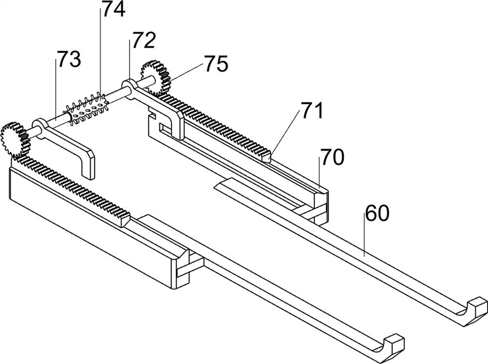
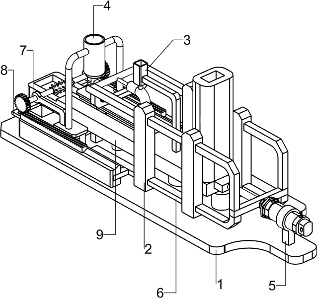
[0066] A device for lens cleaning, such as figure 1 As shown, it includes a base 1, a support 2, a detergent adding mechanism 3, a flushing mechanism 4 and a cleaning frame 9. Two supports 2 are connected to the front and rear sides of the upper part of the base 1, and the upper side of the base 1 is connected to a cleaning frame 9. Cleaning The frame 9 is located on the left side of the support 2, the detergent adding mechanism 3 is slidably connected between the support 2, and the flushing mechanism 4 is connected between the front and rear sides of the upper part of the base 1.

[0067] When the device needs to be used, the user can place the lens in the cleaning frame 9, add detergent to the detergent adding mechanism 3, pour clean water into the flushing mechanism 4, and the user can pull the detergent to the left to add Mechanism 3, and then push the detergent adding mechanism 3 to the right, at this time, the detergent can drop from the detergent adding mechanism 3 to t...

Embodiment 2

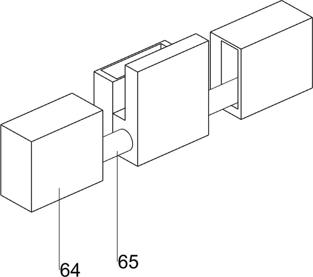
[0069] On the basis of Example 1, such as figure 2As shown, the detergent adding mechanism 3 includes a push rod 30, a support rod 31, a detergent bin 32, a moving rod 33, a piston 34 and an L-shaped pipe 35, and the upper parts of the two brackets 2 on the same side are slidingly connected. There is a push rod 30, a moving rod 33 is connected between the inner side of the left part of the pushing rod 30, a piston 34 is connected to the right side of the moving rod 33, an L-shaped pipe 35 is connected to the outside of the piston 34 in a sliding manner, and a washing machine is connected to the upper side of the L-shaped pipe 35. The detergent material box 32 is connected with a support rod 31 on the right side of the detergent material box 32 .

[0070] After the user places the lens in the cleaning frame 9, the detergent is added to the detergent material box 32, the cleaning water is poured into the flushing mechanism 4, the user can pull the moving rod 33 to the left, and...


PUM


Abstract

The invention relates to a cleaning device, in particular to a lens cleaning device. The invention aims to provide the lens cleaning device for automatically cleaning the lens, improving the cleanliness of the lens and enhancing the practicability of the device. According to the technical scheme, the lens cleaning device is characterized in that the lens cleaning device comprises supports, a cleaning frame, a detergent adding mechanism, and a washing mechanism, wherein the two sides of the top of a base are connected with two supports; the top side of the base is connected with the cleaning frame; the detergent adding mechanism is connected between the supports in a sliding manner; and the washing mechanism is connected between the two sides of the top of the base. Through the cooperationof a pushing rod, a detergent box, a moving rod and a piston, the purpose of adding and using detergents is achieved.

Description

technical field [0001] The invention relates to a cleaning device, in particular to a lens cleaning device. Background technique [0002] Lens is a transparent material with one or more curved surfaces made of optical materials such as glass or resin. After being polished, it is often assembled with a spectacle frame to form glasses. It is used to correct the user's vision and obtain a clear vision. The lens is a precision Optical parts need to be cleaned before and after the coating of the optical lens and in the pre-assembly process to meet the product process and quality requirements. [0003] The lens cleaning devices currently on the market have low automation for lens cleaning during production, cumbersome operations, low cleanliness, low lens cleaning efficiency, and low applicability of the lens cleaning devices. Contents of the invention [0004] In order to overcome the shortcomings of low degree of automation and low applicability, the technical problem to be s...

Claims


Application Information

Patent Timeline
Patent Type & Authority Applications(China)
IPC IPC(8): B08B3/02B08B13/00B08B11/00B08B11/04F26B5/14
CPCB08B3/02B08B13/00B08B11/00B08B11/04F26B5/14B08B2203/0217
Inventor 刘怀安
Owner 刘怀安
Learn More