Equipment used for crushing and compressing stainless steel and aluminium materials of security windows
A technology of stainless steel and aluminum for windows, applied in the fields of presses, grain processing, chemical instruments and methods, etc., can solve the problems of cumbersome operation and high degree of manual coordination, and achieve the effect of convenient collection
- Summary
- Abstract
- Description
- Claims
- Application Information
AI Technical Summary
Problems solved by technology
Method used
Image
Examples
Embodiment 1
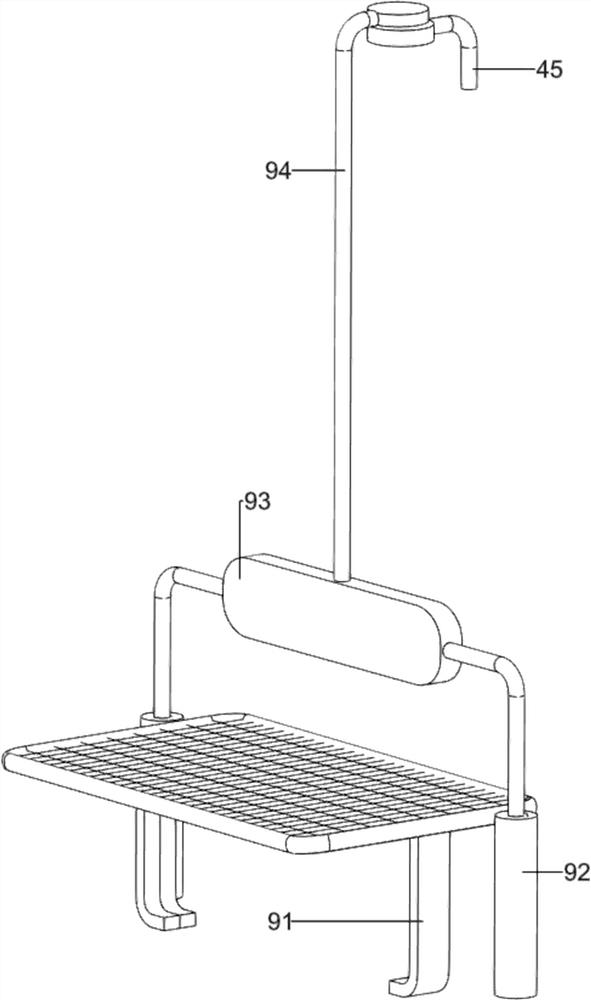
[0062] An anti-theft window stainless steel aluminum crushing equipment, such as figure 1 As shown, it includes a floor 1, a cylinder 2, a push rod 3, a compression mechanism 4, a crushing mechanism 5 and an automatic auxiliary mechanism 6 for crushing. A cylinder 2 is installed on the left rear part of the floor 1, and a push rod 3 is arranged on the top of the cylinder 2. A compression mechanism 4 is provided on the left rear portion of the floor 1, and the compression mechanism 4 is connected to the push rod 3. A crushing mechanism 5 is provided on the right rear portion of the floor 1, and the crushing mechanism 5 is connected to the compression mechanism 4. The part is provided with crushing automatic auxiliary mechanism 6, and compression mechanism 4 and crushing mechanism 5 are all connected with crushing automatic auxiliary mechanism 6.
[0063] When people need to crush and compress the anti-theft window stainless steel and aluminum materials, they can use this crushi...
Embodiment 2
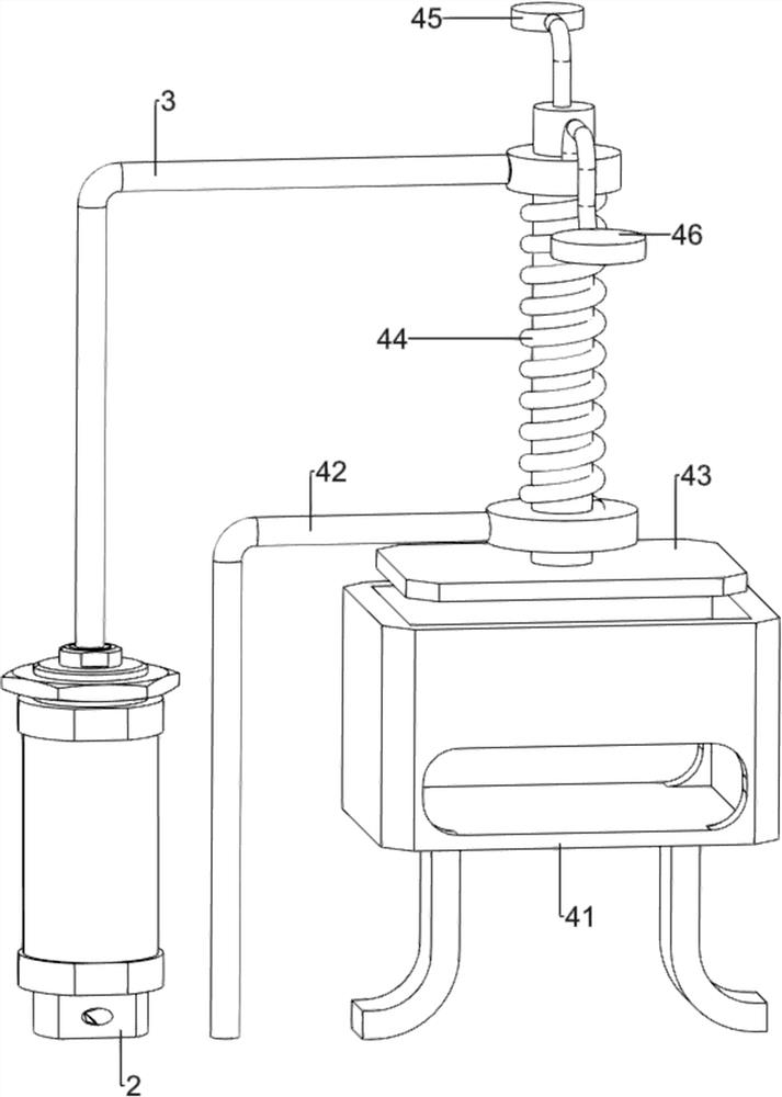
[0065] On the basis of Example 1, such as Figure 2-4 As shown, the compression mechanism 4 includes a compression frame 41, a first fixed support rod 42, a compressor 43, a first spring 44, a first round contact block 45 and a second round contact block 46, and the left rear portion on the floor 1 is provided with There is a compression frame 41, a first fixed support rod 42 is provided on the left rear part of the floor 1, a compressor 43 is provided on the upper part of the push rod 3, and the compressor 43 is slidably connected with the first fixed support rod 42, and the upper part of the compressor 43 is wound around There is a first spring 44, the top of the first spring 44 is connected with the push rod 3, the bottom of the first spring 44 is connected with the first fixed support rod 42, the top of the compressor 43 is provided with a first round contact block 45, and the top of the push rod 3 is on the right side. A second round contact block 46 is provided on the si...
Embodiment 3
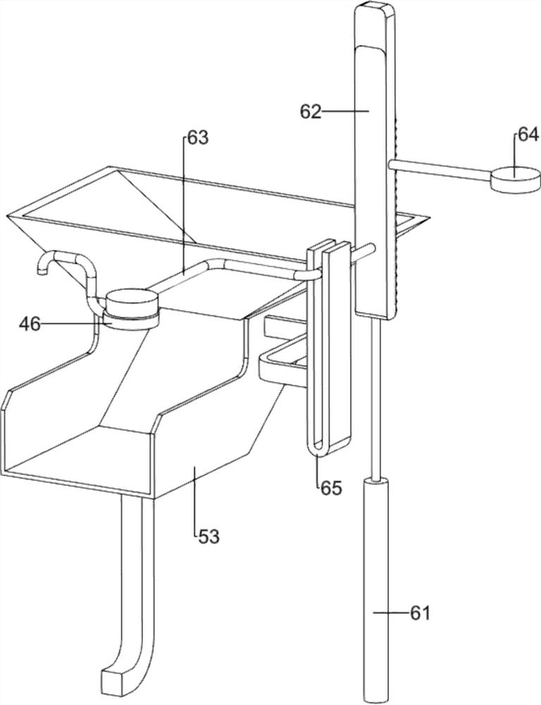
[0072] On the basis of Example 2, such as Figure 5-7 As shown, a pusher mechanism 7 is also included. The left middle part of the floor 1 is provided with a pusher mechanism 7. The pusher mechanism 7 includes a third support block 71, a pusher rod 72, a second spring 73 and a first wedge-shaped length. Block 74, the left middle part on the floor 1 is provided with a third support block 71, the third support block 71 upper sliding pusher rod 72, the pusher rod 72 is slidably connected with the compression frame 41, and the front end of the pusher rod 72 is provided with the first A wedge-shaped long block 74, the front part of the push rod 72 is wound with a second spring 73, and the two ends of the second spring 73 are respectively connected with the third supporting block 71 and the first wedge-shaped long block 74.
[0073] People push the first wedge-shaped long piece 74 backwards, thereby driving the push rod 72 to slide backwards, the second spring 73 is compressed, and ...
PUM
 Abstract
Description
Claims
Application Information
 - R&D
- Intellectual Property
- Life Sciences
- Materials
- Tech Scout
- Unparalleled Data Quality
- Higher Quality Content
- 60% Fewer Hallucinations
Browse by: Latest US Patents, China's latest patents, Technical Efficacy Thesaurus, Application Domain, Technology Topic, Popular Technical Reports.
© 2025 PatSnap. All rights reserved.Legal|Privacy policy|Modern Slavery Act Transparency Statement|Sitemap|About US| Contact US: help@patsnap.com


