
Method and jig for manufacturing equidistant coiled wires

A technology of equal spacing and winding, applied in the manufacture of extensible conductors/cables, etc., can solve the problems of affecting the telephone auscultation effect, the product quality is not ideal, the method is not reasonable enough, etc., to ensure the auscultation effect, the production method is reasonable, and the production convenient effect

Active Publication Date: 2021-03-26
DONGGUAN KAILAI ELECTRONICS CO LTD +1
View PDF5 Cites 1 Cited by
  • Summary
  • Abstract
  • Description
  • Claims
  • Application Information

AI Technical Summary

Problems solved by technology

[0003] The existing method of making coiled wires at equal intervals is unreasonable. For example, a jig with a complex structure is used to position the wires, and each time a coiled wire is made, the work efficiency is low and the operation is relatively complicated; After the heat treatment is completed, bright marks are formed on the inner ring of the coiled wire, resulting in unsatisfactory product quality; in addition, the thread head and thread tail at both ends of the coiled wire are perpendicular to the coiled part, that is, the outlet position is 90°, so that the user When in use, the coiled cord tends to rub against clothing, resulting in an auscultation effect affecting the phone

Method used


Image

  • Method and jig for manufacturing equidistant coiled wires
  • Method and jig for manufacturing equidistant coiled wires
  • Method and jig for manufacturing equidistant coiled wires

Examples


Embodiment Construction

[0016] The present invention will be further described below in conjunction with specific embodiments and accompanying drawings.

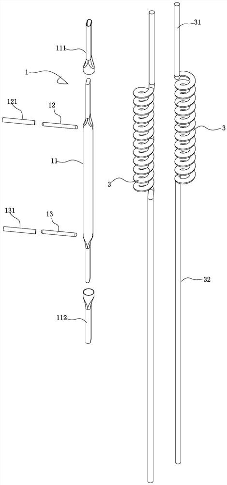
[0017] See Figure 1-3 As shown, it is a method of making equidistant coils, which includes the following steps:

[0018] S001: Prepare jig 1. The jig 1 includes a rolling rod 11 and an upper positioning pin 12 and a lower positioning pin 13 installed horizontally at the upper and lower ends of the rolling rod 11. The surface of the rolling rod 11 is sandblasted, and the roll The outer surfaces of the upper and lower ends of the rod 11 are respectively covered with a first protective sleeve 111 and a second protective sleeve 112; the outer surfaces of the upper positioning pin 12 and the lower positioning pin 13 are respectively sleeved with a third protective sleeve 121 and a second protective sleeve. Four protective sleeves 131;

[0019] S002: Prepare two wires with equal diameters;

[0020] S003: Coiling forming process: Press the ends of the...


PUM


Abstract

The invention discloses a method and jig for manufacturing equidistant coiled wires. The method comprises the following steps that S001, the jig is prepared, the jig comprises a winding bar, an upperpositioning pin and a lower positioning pin, wherein the upper positioning pin and the lower positioning pin are installed at the upper end and the lower end of the winding bar, and sand blasting treatment is conducted on the surface of the winding bar; S002, two electric wires with the same diameter are prepared; S003, wire ends of the two electric wires are pressed on the upper positioning pin in a front-back staggered mode, then positioning is conducted through an upper fixing sleeve piece, meanwhile, the two electric wires are pulled to be attached in parallel, the electric wires are woundon the winding bar clockwise or anticlockwise into a coil until the wire tails of the two electric wires get close to the lower positioning pin, the wire tails of the two electric wires are pressed on the lower positioning pin in a front-back staggered mode, and then a lower fixing sleeve piece is adopted for positioning; S004, a semi-finished product is placed in an oven at the temperature of 120 DEG C to be baked for 25-30 min, and thus the winding part of the electric wires is shaped; S005, the electric wires are taken out after shaping, and placed in clear water to be cooled for 2-3 minutes; and S006, the upper fixing sleeve piece, the lower fixing sleeve piece and the two electric wires are taken down to form the two independent equidistant coiled wires.

Description

Technical field: [0001] The invention relates to the technical field of coiled wire products, in particular to a method and jig for making equidistant coiled wires. Background technique: [0002] The telephone is an inseparable communication tool in human daily life. The telephone includes a telephone part and a handset. , so that the telephone line can be shortened when it is not in use, and it can be automatically reset after being stretched, which is very convenient to use. [0003] The existing method of making coiled wires at equal intervals is unreasonable. For example, a jig with a complex structure is used to position the wires, and each time a coiled wire is made, the work efficiency is low and the operation is relatively complicated; After the heat treatment is completed, bright marks are formed on the inner ring of the coiled wire, resulting in unsatisfactory product quality; in addition, the thread head and thread tail at both ends of the coiled wire are perpend...

Claims


Application Information

Patent Timeline
IPC IPC(8): B21F3/04H01B13/008
CPCB21F3/04H01B13/008
Inventor 左贵明邱武钟旭邓飞飞
Owner DONGGUAN KAILAI ELECTRONICS CO LTD
Learn More