A concrete point compaction system and its application process

A concrete and dense technology, which is applied in the direction of manufacturing tools, ceramic molding machines, supply devices, etc., can solve problems such as left and right shaking, increased construction costs, uneven concrete areas, etc., to reduce manufacturing costs, improve compactness, and compactness. Good results

Active Publication Date: 2021-11-23
中阳建设集团有限公司
View PDF1 Cites 0 Cited by
  • Summary
  • Abstract
  • Description
  • Claims
  • Application Information

AI Technical Summary

Problems solved by technology

[0003]Concrete needs to be poured into the formwork during concrete construction, but due to the friction and cohesion between aggregates, the concrete cannot automatically fill the formwork, and its interior is If it is loose, it is necessary to vibrate the concrete to give the concrete product or structure a certain shape, strength, impermeability and durability. In the prior art, a single vibrating rod is generally used for concrete compaction, which requires workers to The inside of the formwork is slid, and the vibrating rod is manually dragged, which reduces the uniformity of the overall compaction and increases the labor intensity
[0004] The Chinese utility model with the patent number CN201922437722.4 in the prior art discloses a concrete point compaction system, including a mobile chassis device and a lifting A lifting device, a supporting device is installed on the chassis device, and a vibrating device is arranged below the supporting device. Although the concrete point compaction system described in this utility model is convenient for reducing labor intensity, the supporting plate of the device is due to the The steel cable is connected with the support device, so that the support plate of the device will shake left and right and back and forth during use, resulting in uneven concrete area poured by the pouring pipe, and multiple rows of evenly arranged vibrating rods are set to achieve uniform and comprehensive compaction. It increases the construction cost, which is not conducive to meeting the needs of actual use

Method used


Image

  • A concrete point compaction system and its application process
  • A concrete point compaction system and its application process
  • A concrete point compaction system and its application process

Examples


Embodiment 1

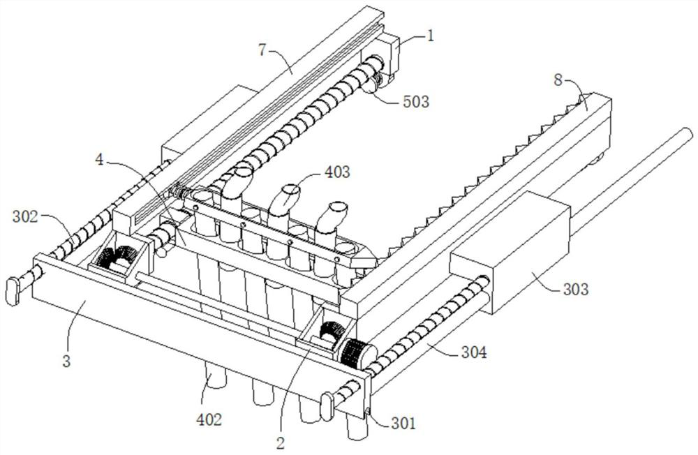
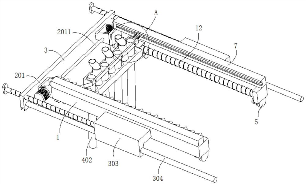
[0040] refer to Figure 1-9 , a concrete point compaction system, comprising two fixing frames 1, the outer walls of the two fixing frames 1 are fixedly connected with a positioning block 303, and the outer wall of the positioning block 303 is rotatably connected with a threaded rod 302 through a first bearing, and the threaded rod 302 is far away from the positioning One end of the block 303 is fixedly connected with a handle 3021, the outer wall of the threaded rod 302 is threadedly connected with a positioning plate 3, the bottom wall of the positioning plate 3 is dug with a draw-in groove 301, the outer wall of the positioning plate 3 is fixedly connected with a guide rod 304, and the positioning block 303 is slidingly connected to the The outer wall of the guide rod 304 and the outer walls of the two fixed frames 1 are fixedly connected with the housing 2, the outer wall of the housing 2 is connected with the first motor 201, the output end of the first motor 201 is connec...

Embodiment 2

[0043] refer to Figure 1-10 , a concrete point compaction system, which is basically the same as that of Embodiment 1, furthermore, both ends of the fixed frame 1 are fixedly connected with connecting plates 5, and the outer walls of the two connecting plates 5 are connected with travel switches 501, two The travel switches 501 are electrically connected to the first motor 201 , and the bottom of the sleeve 122 is connected with a knocking member 6 matched with the travel switches 501 .

[0044] The knocking member 6 includes a knocking rod 601 and two knocking balls 602 , the knocking rod 601 is fixedly connected to the bottom of the sleeve 122 , and the two knocking balls 602 are respectively connected to two sides of the knocking rod 601 .

[0045] The outer wall of the connecting plate 5 is connected with a first elastic element 502, and the end of the first elastic element 502 far away from the connecting plate 5 is connected with a force plate 503, and the outer walls o...

Embodiment 3

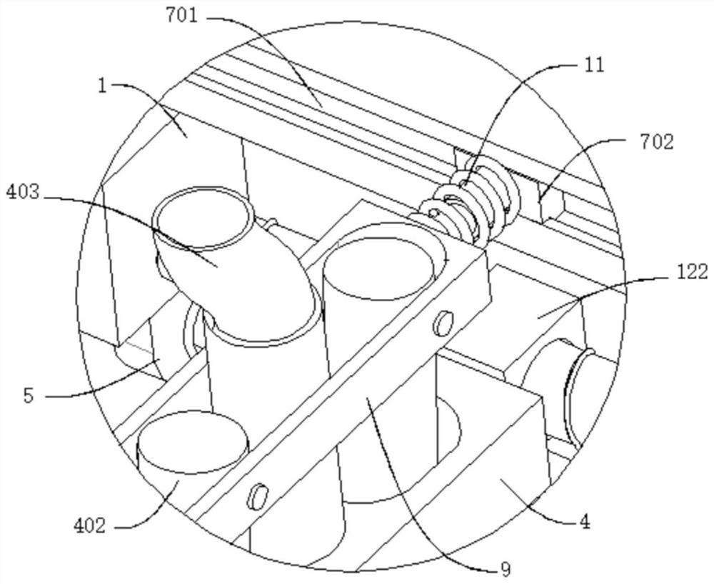
[0048] refer to Figure 1-10 , a concrete point compaction system, which is basically the same as that of Embodiment 2, furthermore, the tops of the two fixing frames 1 are respectively connected with a first connecting block 7 and a second connecting block 8, and the outer wall of the first connecting block 7 is excavated There is a chute 701 , the inner wall of the chute 701 is slidably connected with a slider 702 , and the outer wall of the second connecting block 8 is connected with a protrusion 801 .

[0049] The chute 701 is configured as a convex groove, and the slider 702 is adapted to the chute 701 .

[0050] The top of the vibrating rod 402 is connected with a movable plate 9, and the movable plate 9 is movably connected with the top of the vibrating rod 402 through a pin shaft. One end of the block 10 is connected with a spring telescopic rod 11 , and the end of the spring telescopic rod 11 away from the movable plate 9 is connected to the outer wall of the slider ...


PUM


Abstract

The invention discloses a concrete point compaction system and an application process thereof, which belong to the technical field of concrete construction. A concrete point compacting system, comprising two fixing frames, the outer walls of the two fixing frames are fixedly connected with a positioning block, the outer wall of the positioning block is rotatably connected with a threaded rod through a first bearing, and the end of the threaded rod far away from the positioning block is fixedly connected with a handle , the outer wall of the threaded rod is threadedly connected with a positioning plate, the bottom wall of the positioning plate is dug with a card slot, the outer wall of the positioning plate is fixedly connected with a guide rod, the positioning block is slidably connected with the outer wall of the guide rod, and the outer walls of the two fixing frames are fixedly connected with a shell , the outer wall of the housing is connected with a first motor, and the output end of the first motor is connected with a rotating shaft; the invention fixes the device to make the concrete pouring uniform, and compared with the traditional method of using multiple rows of vibrating rods to achieve all-round compactness According to the scheme, the device effectively reduces the manufacturing cost of the building, and has a good compacting effect.

Description

technical field [0001] The invention relates to the technical field of concrete construction, in particular to a point-by-point compacting system for concrete and an application process thereof. Background technique [0002] Concrete refers to the collective name of engineering composite materials that use cementitious materials to cement aggregates into a whole. The term concrete usually refers to the use of cement as cementitious material, sand and stone as aggregates, and water (may contain additional Cement concrete, also known as ordinary concrete, is widely used in civil engineering. [0003] During concrete construction, concrete needs to be poured into the formwork first, but due to the friction and cohesion between the aggregates, the concrete cannot automatically fill the formwork, and the interior is loose. At this time, the concrete needs to be vibrated to form the concrete The product or structure has a certain shape, strength, impermeability and durability. In...

Claims


Application Information

Patent Timeline
Patent Type & Authority Patents(China)
IPC IPC(8): B28B1/04
CPCB28B1/045B28B13/02
Inventor 李建朱霖平彭文强姚纪连夏知福
Owner 中阳建设集团有限公司
Why Eureka
Try Eureka