
Automobile seat

A car seat and seat frame technology, which is applied to vehicle seats, seat frames, movable seats, etc., can solve the problems of increasing the length of the rear panel of the seat frame, insufficient foot space, and increasing costs, and achieves simplification The installation structure, the structure is simple and effective, and the effect of increasing the foot space

Active Publication Date: 2021-03-26
CHONGQING YANFENG ADIENT AUTOMOTIVE COMPONENTS CO LTD
View PDF6 Cites 0 Cited by
  • Summary
  • Abstract
  • Description
  • Claims
  • Application Information

AI Technical Summary

Problems solved by technology

[0003]1. When the front of the seat is upturned, the existing support structure cannot guarantee effective support for the front of the seat;
[0004]2. The linkage structure between the seat cushion and the backrest is complicated, and the lower part of the seat usually cannot be rotated, and is separated from the backrest of the seat, so linkage cannot be performed;
[0005] 3. The front part of the lower connection plate of the traditional recliner is directly connected to the side plate of the seat frame, and then the side plate of the seat frame is connected to the slide rail; the position of the recliner is relatively high, and the recliner is located above the seat frame or basically flat Qi, the front space of the seat frame body is small, and the foot space is insufficient;
[0006]4. When increasing the area of ​​the seat frame, it is necessary to increase the length of the rear panel of the seat frame, which increases the cost, weight and occupied space;
[0007]5. Place foam on the top of the traditional seat frame, place foam in front of the backrest frame, then cover the outside with a cover, set a hook on the edge of the cover, and hang the hook on the frame to adjust the foam For support and hooking with the cover, the required seat pan frame is usually steel, and a large number of steel wires need to be installed, and its structure is complex and heavy

Method used


Image

  • Automobile seat
  • Automobile seat
  • Automobile seat

Examples


Embodiment Construction

[0066] The present invention will be further described below in conjunction with embodiment and accompanying drawing.

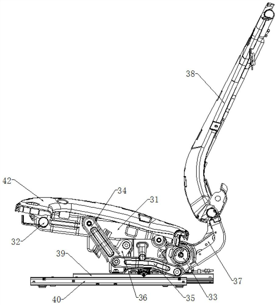
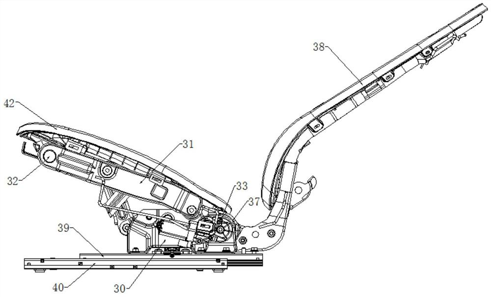
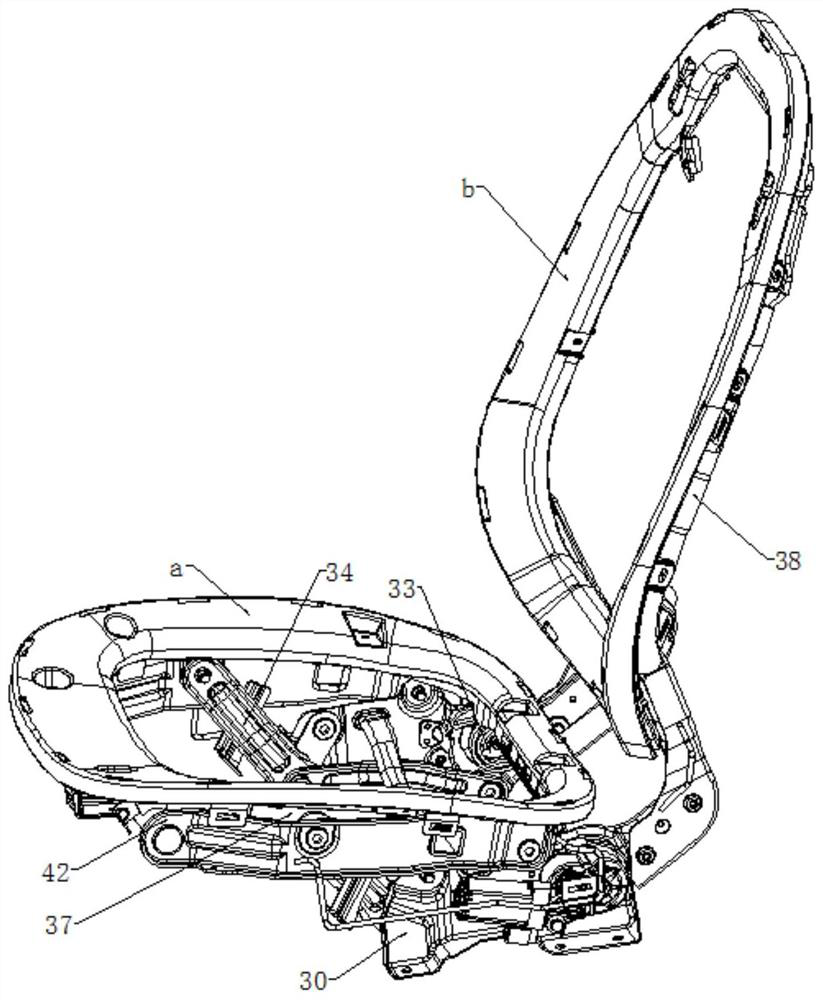
[0067] Such as Figure 1 to Figure 23 As shown, a car seat mainly includes an installation base, a seat cushion, a backrest, a linkage and a power unit, the rear part of the seat cushion and the lower part of the backrest are hinged to the installation base, and the The seat cushion and the backrest are connected through the linkage;

[0068] The installation base includes two sliding rails facing oppositely, and the upper surfaces of the sliding rails are respectively provided with mounting parts, and the power device is installed on any one of the mounting parts, and the power device drives the backrest rotation;

[0069] Described linkage comprises upper hinged rod 34, lower hinged rod 35 and connecting rod 36, and one end of described upper hinged rod 34 is hinged with the front portion of described seat frame 42, and the other end of described upper hi...


PUM


Abstract

The invention discloses an automobile seat which comprises an installation base, a seat cushion, a backrest, a linkage piece and a power device, the rear portion of the seat cushion and the lower portion of the backrest are hinged to the installation base, the seat cushion and the backrest are connected through the linkage piece, the installation base comprises two sliding rails arranged oppositely, and the upper surfaces of the sliding rails are further provided with installation pieces respectively. The power device is installed on any installation piece and drives the backrest to rotate, the cushion comprises a seat frame and a seat frame supporting ring, the seat frame supporting ring is installed on the upper portion of the seat frame, the backrest comprises a backrest frame and a backrest supporting ring, and the backrest supporting ring is installed on the front portion of the backrest frame. According to the automobile seat, brand-new design and structure are adopted, and the angle adjuster core part rotates, so that in the backrest adjusting process, the linkage part can drive the cushion to be adjusted at the same time, meanwhile, the installation structure of the angle adjuster lower connecting plate and the sliding rail is simplified, the front portion of the seat frame body is suspended, and the foot space is enlarged.

Description

technical field [0001] The invention relates to a car seat, in particular to a car seat. Background technique [0002] Car seat belongs to the basic device of the car and is an important safety part of the car. In the car, it connects the human body and the body, which is directly related to the comfort and safety of the occupants. With the development of society and the improvement of people's economic level , the penetration rate of automobiles is getting higher and higher. During the use of automobiles, facing different users and different environments, new demands will continue to be generated. Facing various demands, it is necessary to design a large number of For this reason, various new structures have been produced, such as the seat frame with the linkage between the seat and the backrest. When designing this product, due to new requirements and mechanisms, it is necessary to redesign the corresponding New parts, for this reason, when facing the situation that the s...

Claims


Application Information

Patent Timeline
IPC IPC(8): B60N2/68B60N2/22B60N2/02B60N2/10
CPCB60N2/682B60N2/22B60N2/10B60N2002/684B60N2/02246
Inventor 龙德学杨双华惠海岗苟华刚唐杰
Owner CHONGQING YANFENG ADIENT AUTOMOTIVE COMPONENTS CO LTD
Learn More