Optical module, manufacturing method therefor, protective component for a light guide, and protective component having electric wiring

A technology of optical modules and electrical wiring, applied in the field of optical modules, can solve the problems of unfavorable size reduction and cost reduction, and achieve the effects of size reduction, cost reduction, and simple installation structure

Inactive Publication Date: 2005-09-14
FUJITSU LTD
View PDF1 Cites 13 Cited by
  • Summary
  • Abstract
  • Description
  • Claims
  • Application Information

AI Technical Summary

Problems solved by technology

[0005] However, the first conventional example described above requires not only a large number of components but also a large number of optical axis adjustment points, which is disadvantageous in size reduction and cost reduction
[0006] On the other hand, the second conventional example considers carrying an end face light-receiving / emitting type optical element, and therefore, it is not suitable for carrying a standard, low-cost PIN-PD (PIN-Photodiode)

Method used


Image

  • Optical module, manufacturing method therefor, protective component for a light guide, and protective component having electric wiring
  • Optical module, manufacturing method therefor, protective component for a light guide, and protective component having electric wiring
  • Optical module, manufacturing method therefor, protective component for a light guide, and protective component having electric wiring

Examples


no. 1 example

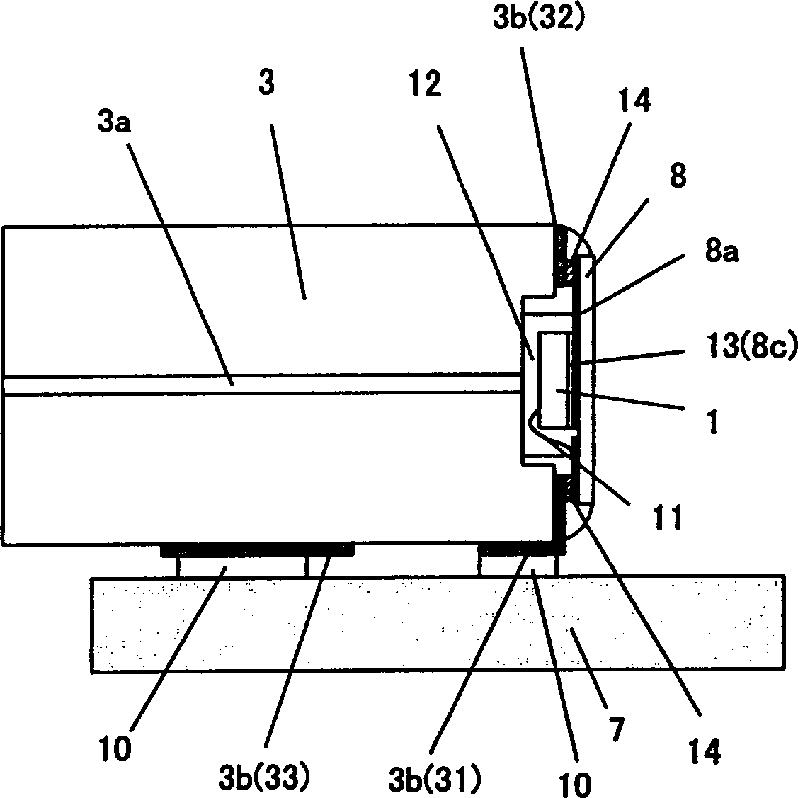
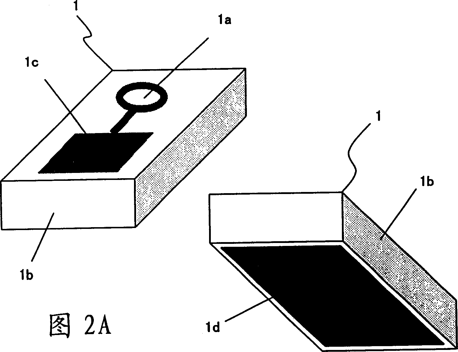
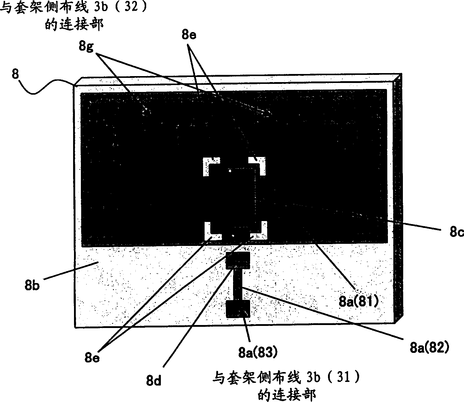
[0040] figure 1 is a partially transparent side view illustrating the construction of an optical module according to a first embodiment of the invention. 2(A) and 2(B) are perspective views schematically showing optical elements used as main components of the optical module, image 3 is a perspective view schematically showing a base (an optical element mounting substrate) on which the optical element is loaded (mounted), and Figure 4 is a perspective view schematically showing a holder serving as a main component of the optical module.

[0041] exist figure 1 Among them, the optical module includes the following main components: a base 8 on which an optical element 1 is mounted, for example, a light-emitting element such as an LD or a light-receiving element such as a PD, which are used to perform photoelectric conversion; and a sheath (protective component )3, used to protect optical fibers used as optical transmission media. In addition, in figure 1 In , reference ...


PUM


Abstract

According to the present invention, there is provided a manufacturing method for an optical module made up of an optical element (1), a protective component (3) for protecting an optical transmission medium (3a) to be optically coupled to the optical element (1) and an electric wiring (3b) formed on the protective component (3) in conjunction with the optical element (1).

Description

technical field [0001] The present invention relates to an optical module, a manufacturing method of the module, a protection assembly, and a protection assembly with electrical wiring, for example, to an optical transmission module and an optical reception module suitable for use in data transmission in next-generation server systems and the like Technology. Background technique [0002] Since data transmission in a server system relies on massively parallel transmission, a large number of optical modules need to be installed in parallel. This requires size reduction and cost reduction for each optical module. [0003] As a first conventional example, Figure 22 A CAN package type optical module for optical communication is shown. Such as Figure 22 As shown, a conventional CAN packaged optical module includes the following main components: an optical element 100 such as a laser diode (LD) or a photodiode (PD), (two) lenses 200, a sleeve 300 for protecting an optical fibe...

Claims


Application Information

Patent Timeline
Patent Type & Authority Applications(China)
IPC IPC(8): G02B6/12G02B6/26G02B6/36G02B6/42H01L31/0232H01R4/04H01R13/46H01R43/00H01S5/022
CPCG02B6/4202
Inventor 寺田浩二松井润延原裕之
Owner FUJITSU LTD
Why Eureka
Try Eureka