Method for estimating transient soot emission of engine

An emission and engine technology, applied in the direction of engine testing, measuring devices, machine/structural component testing, etc., can solve the difficulties of transient soot flow estimation, no load correction coefficient type, exhaust transient soot flow error and other problems, to achieve the effect of comprehensive calibration quantitative factors, clear correction factors, and high relative accuracy

Active Publication Date: 2021-03-26
DONGFENG MOTOR CORP HUBEI
View PDF7 Cites 2 Cited by
  • Summary
  • Abstract
  • Description
  • Claims
  • Application Information

AI Technical Summary

Problems solved by technology

The soot flow in the exhaust is generally divided into the flow in the steady state and the flow in the transient state. The steady-state soot flow in the exhaust can be accurately estimated through the existing calibration logic, but it is difficult to estimate the transient soot flow. Existing logic strategies have large errors in estimating exhaust transient soot flow
[0004] Chinese patent application CN108087071A describes a method for calculating the soot transient emission in the method for judging the carbon load of DPF, which is obtained by complex correction of the soot steady-state emission; at the same time, the patent application does not load the correction coefficient type

Method used


Image

  • Method for estimating transient soot emission of engine
  • Method for estimating transient soot emission of engine

Examples


Embodiment Construction

[0024] The following specific implementation methods are used to explain the technical solutions of the claims of the present invention, so that those skilled in the art can understand the claims. The protection scope of the present invention is not limited to the following specific implementation structures. The protection scope of the present invention includes the technical solution of the claims of the present invention made by those skilled in the art and is different from the following specific embodiments.

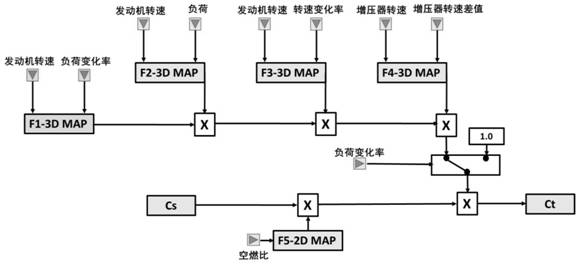
[0025] In the calibration process of the present invention, corrections under different operating conditions can be considered.

[0026] The load change rate correction factor F1 takes into account the impact of different load change rates on transient soot emissions. Because the load change will affect the actual air-fuel ratio, the uniformity of the mixture, and the uniformity of the intake air of each cylinder, which will greatly affect the adequacy of combustio...


PUM


Abstract

The invention discloses a method for estimating the transient soot emission of an engine. The method comprises the following steps: firstly, acquiring a first steady-state soot emission Cs data set ofan engine at different rotating speeds and a second steady-state soot emission Cs data set of the engine at different air-fuel ratios through a bench test; correcting the first steady-state soot emission Cs data to obtain an estimated value of the transient-state soot emission of the engine, wherein the correction method comprises a product of the first steady-state soot emission Cs and a correction coefficient factor; wherein the correction coefficient factors comprise at least three of a load change rate correction coefficient F1, a load correction coefficient F2, an engine rotating speed change rate correction coefficient F3, an air-fuel ratio correction coefficient F5 and a supercharger rotating speed correction coefficient F4, and the correction coefficient factors comprise the air-fuel ratio correction coefficient F5. The correction method is simple, and correction factors are clear and comprehensive. According to the method for estimating the transient soot emission, the calibration of the transient soot emission is completed, the calibration quantity factors are comprehensive, the calibration quantity is large, and the relative precision is high during application.

Description

technical field [0001] The invention belongs to engine electronic control technology, and in particular relates to a technology for obtaining engine transient soot emission. Background technique [0002] The gasoline engine particulate filter GPF has been widely used to solve vehicle emission problems and improve the environmental friendliness of vehicles. During the operation of the vehicle, the gasoline engine particulate filter GPF can capture most of the particulate matter soot. If it runs at low temperature and low speed for a long time, soot will quickly accumulate and block the GPF, affecting engine power and even burning the GPF. [0003] In order to avoid the blockage or burnout caused by the excessive accumulation of carbon in the GPF, the technical scheme of active regeneration is usually adopted in the prior art to purify the carbon accumulation in the GPF. The specific ECU calculates the carbon load in the GPF by calculating the soot flow in the exhaust gas. W...

Claims


Application Information

Patent Timeline
Patent Type & Authority Applications(China)
IPC IPC(8): G01M15/00G01M15/02
CPCG01M15/00G01M15/02
Inventor 张翼邹亚陈龙王静波
Owner DONGFENG MOTOR CORP HUBEI
Why Eureka
Try Eureka