
Target shooting device and method

A technology of a photographing device and a photographing method, which is applied to measurement devices, reflection/re-radiation of radio waves, television, etc., and can solve problems such as inability to track target objects and single photographing range.

Active Publication Date: 2021-03-26
MOBILE DRIVE NETHERLANDS BV
View PDF10 Cites 0 Cited by
  • Summary
  • Abstract
  • Description
  • Claims
  • Application Information

AI Technical Summary

Problems solved by technology

[0002] The shooting range of the existing camera device is single, and when the target object moves out of the shooting range of the camera device, the camera device cannot track the target object

Method used


Image

  • Target shooting device and method
  • Target shooting device and method
  • Target shooting device and method

Examples


Embodiment Construction

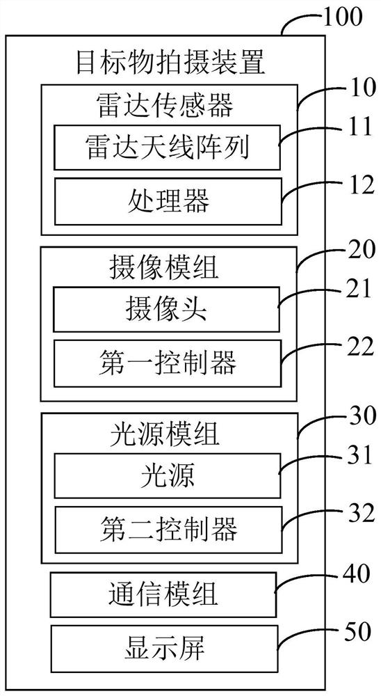
[0033] figure 1 A target shooting device 100 in a preferred embodiment of the present invention is shown, which can be applied to multiple scenes that require tracking and shooting of targets. The object photographing device 100 includes a radar sensor 10 and at least one camera module 20 .

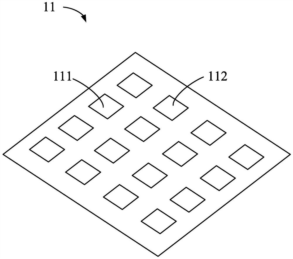
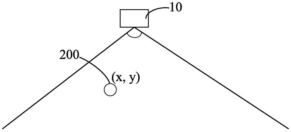
[0034] The radar sensor 10 is used for detecting spatial position information of at least one target 200 . Please also refer to figure 2 , in this embodiment, the radar sensor 10 is a millimeter-wave radar sensor operating in the millimeter-wave band, which includes a radar antenna array 11 and a processor 12 . The radar antenna array 11 includes multiple transmitting antennas 111 and multiple receiving antennas 112 . The processor 12 is electrically connected to the receiving antenna 112 . More specifically, the radar antenna array 11 is a microstrip array antenna. The microstrip array antenna has the characteristics of high gain, low sidelobe and miniaturization, and can realize hi...


PUM


Abstract

The embodiment of the invention provides a target object shooting device, which comprises a radar sensor used for detecting the spatial position information of at least one target object; and at leastone camera module, wherein each camera module is used for obtaining the spatial position information of one target object, and adjusting the shooting range and zoom distance of the camera module according to the spatial position information. And the camera module is also used for acquiring an image of the target object after the shooting range and the zooming distance are adjusted. The embodimentof the invention also provides a target shooting method.

Description

technical field [0001] The present invention relates to image shooting, in particular to a target shooting device and a target shooting method. Background technique [0002] The photographing range of the existing photographing device is single, and when the target object moves out of the photographing range of the photographing device, the photographing device cannot track the target object. Contents of the invention [0003] In view of this, it is necessary to provide a device and method capable of automatically tracking the shooting target, so as to solve the above problems. [0004] An embodiment of the present invention provides a target shooting device, including: [0005] a radar sensor for detecting spatial position information of at least one target; and [0006] At least one camera module, each camera module is used to obtain the spatial position information of one of the targets, adjust the shooting range and zoom distance of the camera module according to the...

Claims


Application Information

Patent Timeline
Patent Type & Authority Applications(China)
IPC IPC(8): H04N5/232G01S13/06
CPCG01S13/06H04N23/67H04N23/695
Inventor 黄柏华林钟权
Owner MOBILE DRIVE NETHERLANDS BV
Learn More