
Coating stirring device and coating stirring method for building construction

A technology for building construction and mixing device, which is applied in mixer accessories, chemical instruments and methods, transportation and packaging, etc., can solve the problems of low mixing efficiency and single mixing method, and achieves improved mixing efficiency, improved mixing efficiency, and good mixing efficiency. Effect

Inactive Publication Date: 2021-03-30
陈昕昳
View PDF0 Cites 3 Cited by
  • Summary
  • Abstract
  • Description
  • Claims
  • Application Information

AI Technical Summary

Problems solved by technology

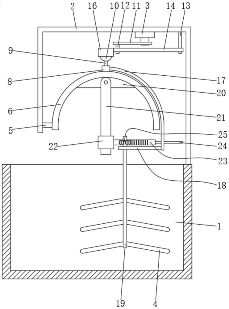
[0004] The object of the present invention is to provide a paint stirring device and a stirring method for building construction, which has a single driving source, which can drive the stirring rod to swing back and forth, left and right, and reciprocate and rotate at the same time, greatly improving the mixing efficiency of paint stirring. It solves the problem that the existing paint stirring method is usually carried out by using a stirring rod that rotates in one direction, and the stirring method is relatively single, resulting in relatively low stirring efficiency

Method used


Image

  • Coating stirring device and coating stirring method for building construction
  • Coating stirring device and coating stirring method for building construction
  • Coating stirring device and coating stirring method for building construction

Examples


Embodiment Construction

[0029] The following will clearly and completely describe the technical solutions in the embodiments of the present invention with reference to the accompanying drawings in the embodiments of the present invention. Obviously, the described embodiments are only some, not all, embodiments of the present invention. Based on the embodiments of the present invention, all other embodiments obtained by persons of ordinary skill in the art without making creative efforts belong to the protection scope of the present invention.

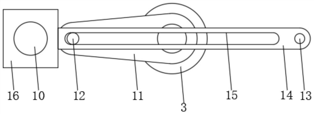
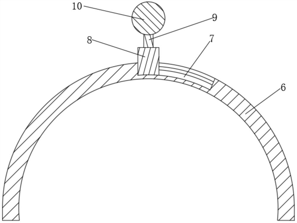
[0030] see Figure 1 to Figure 4 , the present invention provides a technical solution: a paint stirring device for building construction, comprising a box body 1, the upper surface of the box body 1 is fixedly connected with a support frame 2, and the surface of the support frame 2 is fixedly connected with a rotating The driving source 3 also includes a transmission mechanism 1, driven by the rotating drive source 3, and under the action of the transmission ...


PUM


Abstract

The invention discloses a coating stirring device for building construction, belonging to the technical field of coating production. The coating stirring device comprises a box body, wherein the uppersurface of the box body is fixedly connected with a support frame, and the surface of the support frame is fixedly connected with a rotation driving source. The coating stirring device further comprises a transmission mechanism I. Through the driving of the rotation driving source and under the action of the transmission mechanism I, a stirring rod is driven to swing front and back. The coating stirring device also comprises a transmission mechanism II. Through the driving of the rotation driving source and under the co-action of the transmission mechanism I the transmission mechanism II, thestirring rod is driven to swing left and right while swinging front and back. According to the coating stirring device, the stirring rod can be driven to swing front and back and swing left and rightthrough a single driving source, and meanwhile, reciprocating autorotation is realized, so the mixing efficiency of coating stirring is greatly improved, and the device overcomes the problem that stirring efficiency is low in the prior art since existing coating stirring modes normally adopt stirring rods rotating in a single direction and a stirring mode is single.

Description

technical field [0001] The invention relates to the technical field of paint production, in particular to a paint stirring device and a stirring method for building construction. Background technique [0002] Paint manufacturers usually mix and disperse several substances in a certain proportion when preparing paint. [0003] The existing paint stirring methods usually use a stirring rod that rotates in one direction, and the stirring method is relatively single, resulting in relatively low stirring efficiency. Contents of the invention [0004] The object of the present invention is to provide a paint stirring device and a stirring method for building construction, which has a single driving source, which can drive the stirring rod to swing back and forth, left and right, and reciprocate and rotate at the same time, greatly improving the mixing efficiency of paint stirring. The method solves the problem that in the existing paint stirring method, a stirring rod rotating ...

Claims


Application Information

Patent Timeline
Patent Type & Authority Applications(China)
IPC IPC(8): B01F15/00B01F11/00
CPCB01F31/443B01F35/00B01F2101/30
Inventor 陈昕昳
Owner 陈昕昳
Learn More