
Full-automatic numerical control shot blasting machine

A kind of shot blasting machine, fully automatic technology, applied in the direction of abrasive jet machine tool, used abrasive processing device, explosion generating device, etc., can solve the problem that it takes a long time to process steel bars, increase energy consumption and production cost, and waste human resources And other problems, to achieve the effect of not easy to shoot dead angle, increase the shot blasting area, and increase the probability

Active Publication Date: 2021-03-30
山东盛德机械有限公司
View PDF18 Cites 3 Cited by
  • Summary
  • Abstract
  • Description
  • Claims
  • Application Information

AI Technical Summary

Problems solved by technology

[0005] In order to make up for the deficiencies of the existing technology, when the shot blasting machine cleans and derusts various waste workpieces containing steel bars, due to the long length of the steel bars, it is easy to deform and entangle with other workpieces during the processing process. It takes a long time to process the finished steel bars, resulting in a waste of human resources, and in the process of throwing and beating, it is easy to have insufficient beating and most shot blasting machines need to recycle the scattered steel shots through the hoist, which greatly improves the performance. Consumption and production cost problems, a kind of fully automatic numerical control shot blasting machine proposed by the present invention

Method used


Image

  • Full-automatic numerical control shot blasting machine
  • Full-automatic numerical control shot blasting machine
  • Full-automatic numerical control shot blasting machine

Examples


Embodiment approach

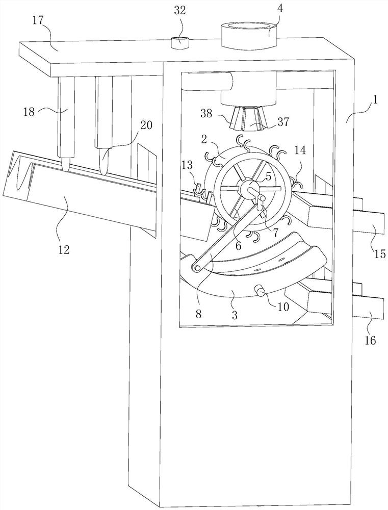
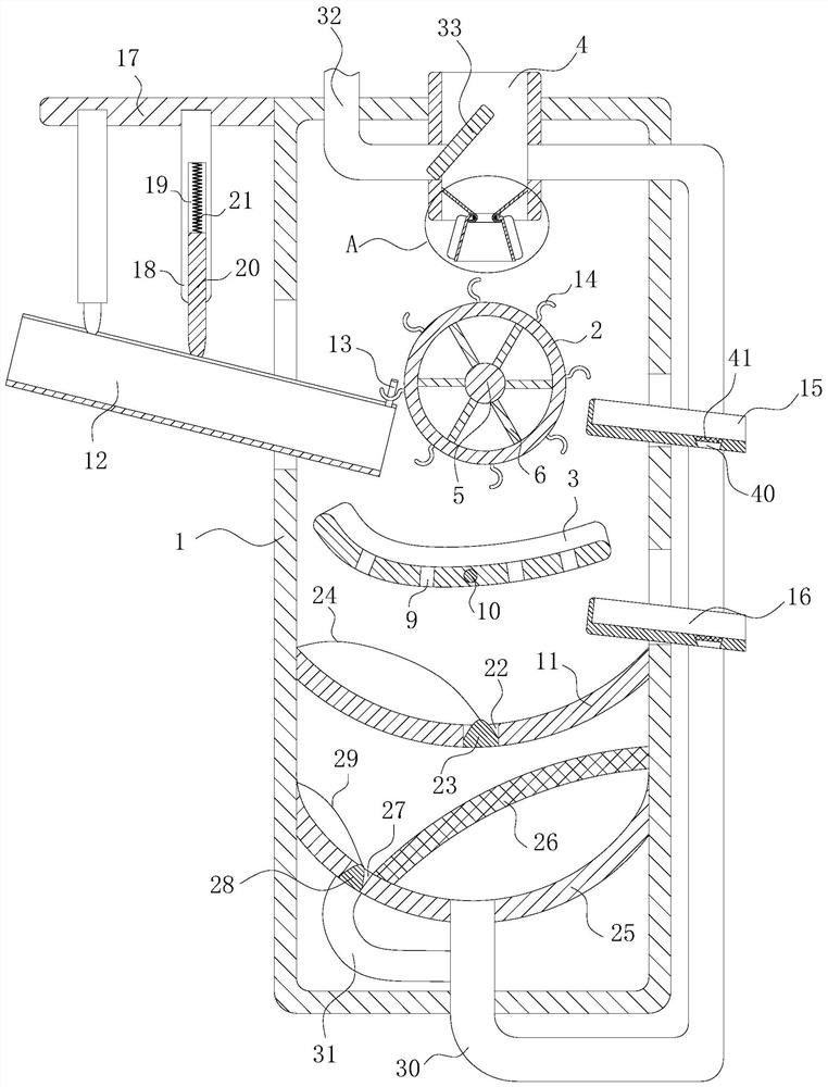
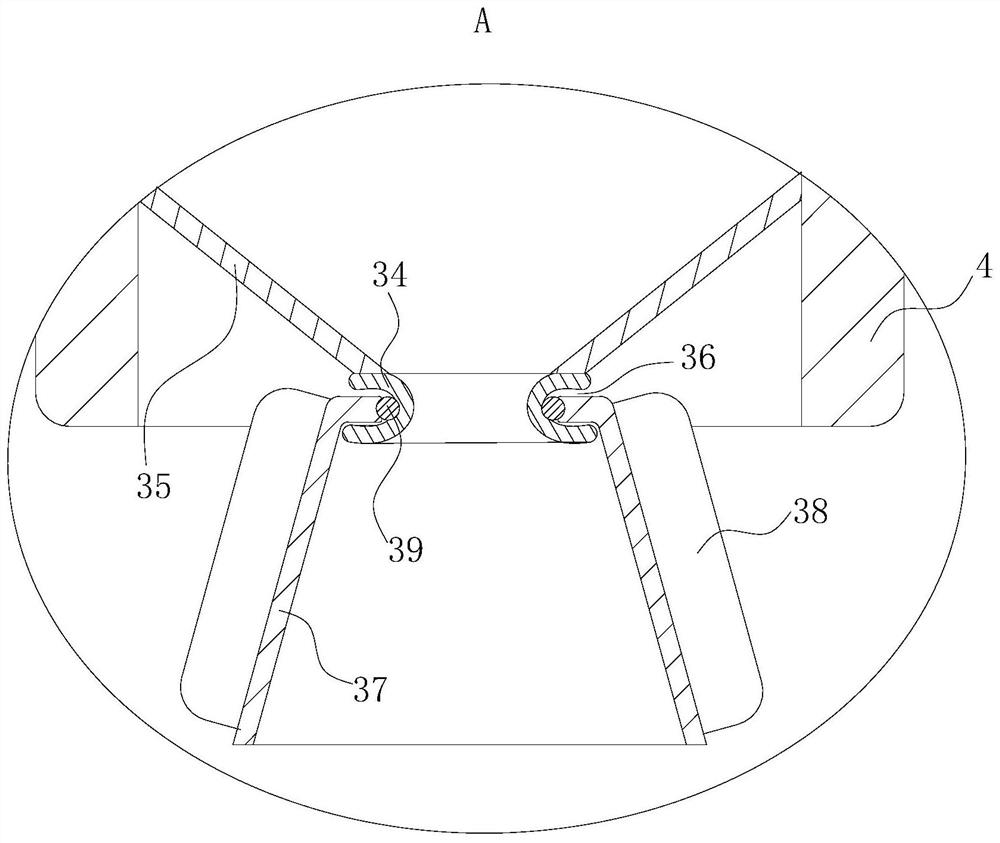
[0023] As an embodiment of the present invention, the upper left end of the housing 1 is fixedly connected with a mounting plate 17, and the lower surface of the mounting plate 17 is provided with a chute, and the number of the chute is two, and the two chute are arranged left and right. ; In the chute, slide bars 18 are slidably connected. In the initial state, two slide bars 18 are located at the front end and the rear end of the chute respectively, and the slide bars 18 are fixedly connected with the front and rear side walls of the chute respectively. There is an electric telescopic rod, which drives two sliding rods 18 to move toward each other when the electric telescopic rod moves; the inside of the lower end of the sliding rod 18 is provided with a sliding groove 19, and a sliding rod 20 is slidably connected in the sliding groove 19. The lower end of the sliding rod 20 is a tapered design, and a spring 21 is fixedly connected between the sliding rod 20 and the inner wa...


PUM


Abstract

The invention belongs to the technical field of shot blasting machines, and particularly relates to a full-automatic numerical control shot blasting machine. The full-automatic numerical control shotblasting machine comprises a shell, a roller, an arc-shaped plate and a feeding plate, wherein a feeding cylinder is arranged in the center of the upper surface of the shell; the roller is arranged under the feeding cylinder, and a first rotating shaft is arranged in the center of the roller; a rocker designed to be shaped like a Chinese character "gong" is arranged in front of the first rotatingshaft; the arc-shaped plate is arranged under the roller; a connecting rod is hinged between the left end of the arc-shaped plate and the central concave part of the rocker; a collecting plate is arranged below the arc-shaped plate; a feeding opening is formed in the middle of the roller on the left side wall of the shell, and an obliquely designed feeding plate is arranged at the feeding opening;and the cross section of the feeding plate is in a waveform design, and the wave crest of the end, close to the roller, of the feeding plate is fixedly connected with a fixing rod. Through the mutualcooperation of the feeding plate, the roller and the arc-shaped plate, automatic classification of steel bars and other workpieces is achieved, the post-processing time is saved, and resource waste is reduced.

Description

technical field [0001] The invention belongs to the technical field of shot blasting machines, in particular to a fully automatic numerical control shot blasting machine. Background technique [0002] Shot blasting machine refers to casting equipment that uses high-speed projectiles thrown by a shot blaster to clean or strengthen the surface of castings. The shot blasting machine can shake out sand, remove core and clean the casting at the same time. In the production of general castings, shot peening cleaning is an indispensable process to find surface defects of castings such as subcutaneous pores, slag pores, sand sticking, cold shut, peeling, etc. The surface cleaning of non-ferrous metal castings, such as aluminum alloys, copper alloys, etc., in addition to removing scale and finding surface defects of castings, the main purpose is to remove burrs of die castings and obtain decorative surface quality by shot blasting , to obtain a comprehensive effect, compared with o...

Claims


Application Information

Patent Timeline
Patent Type & Authority Applications(China)
IPC IPC(8): B24C3/00B24C5/06B24C9/00
CPCB24C3/00B24C5/06B24C9/00B24C9/003B24C9/006
Inventor 樊锟梁涛方舟
Owner 山东盛德机械有限公司
Learn More