
Eureka
For R&D, Eureka makes reading and utilizing patents & technical documents easy.
Eureka AIR
Designed for self-driven R&D workflows. Generate viable solutions, solve complex R&D challenges, empower your innovation with AI.

Eureka Materials
Designed for material experts only. Revolutionize your material R&D, from search, analyze, to developing new materials.

TechResearch
Generate reliable direction feasibility study reports for your R&D in just a few steps.

TechSeek
Discover and master advanced knowledge NOW. Basics, ideas, possibilities, all at once.

TechMind
As an expert in R&D Theories, TechMind can generates customized viable solutions instantly.

TechRisk
Analyze your overall solution with one click, know your potential R&D risks in advance.

TechMonitor
Get weekly tech updates, stay abreast of the latest tech innovations and key insights.
Auxiliary hoisting device based on existing profile steel and mounting method
An auxiliary crane and section steel technology, which is applied in the direction of transportation and packaging, load hanging components, etc., can solve the problems of time-consuming, money-consuming, work space occupation, and long time occupation, and achieve the effect of flexible application position and easy sliding
- Summary
- Abstract
- Description
- Claims
- Application Information
AI Technical Summary
Problems solved by technology
Method used
Image

Examples
Embodiment 1
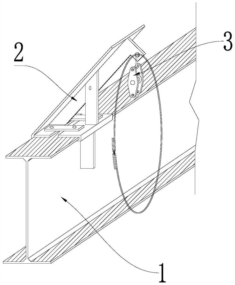
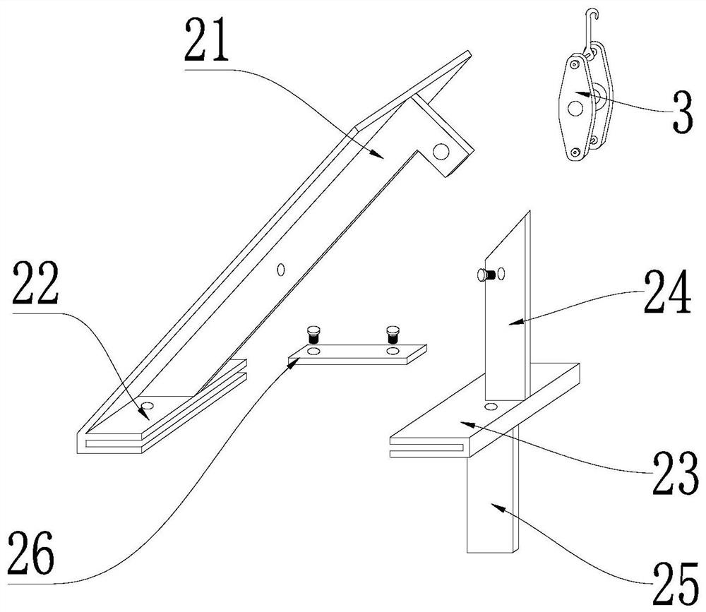
[0025] Example 1: See Figure 1 to Figure 4 , the auxiliary hoisting device based on the existing shaped steel in this embodiment includes a hoisting assembly 2, the hoisting assembly 2 includes a first plywood 22 and a second plywood 23 for snapping on both sides of the shaped steel 1, the first plywood 22 1. The second plywood 23 is slidingly connected to the section steel 1. The first plywood 22 and the second plywood 23 are detachably fixed by the fixing plate 26. The first plywood 22 is provided with an inclined suspender 21, an inclined suspender 21 The end far away from the first plywood 22 is provided with a lifting device 3 for lifting the product 4, the second plywood 23 is fixed with a support rod 24, and the end of the support rod 24 away from the second plywood 23 is fixed on the middle of the inclined boom 21 Location. Set the hoisting component 2 on the existing installed main section steel 1, and install the fixed pulley or wire rope on the hoisting component ...
Embodiment 2
[0026] Embodiment 2: the fixing plate 26 of this embodiment is provided with a first threaded hole and a second threaded hole, the first clamping plate 22 is provided with a third threaded hole for connecting with the first threaded hole, and the second clamping plate 23 A fourth threaded hole for connecting with the second threaded hole is arranged on the top. Easy to assemble and disassemble. There are two fixing plates 26 in this embodiment, which are distributed on both sides of the inclined suspender 21 . Strengthen the connection stability between the first plywood 22 and the second plywood 23 . The bottom of the second plywood 23 in this embodiment is provided with a supporting plate 25 , and the supporting plate 25 is used for abutting against the shaped steel 1 . Strengthen the stability of the overall structure. The support plate 25 , the second plywood 23 and the support rod 24 in this embodiment are a fixed integral structure. They are all formed by welding ste...
Embodiment 3
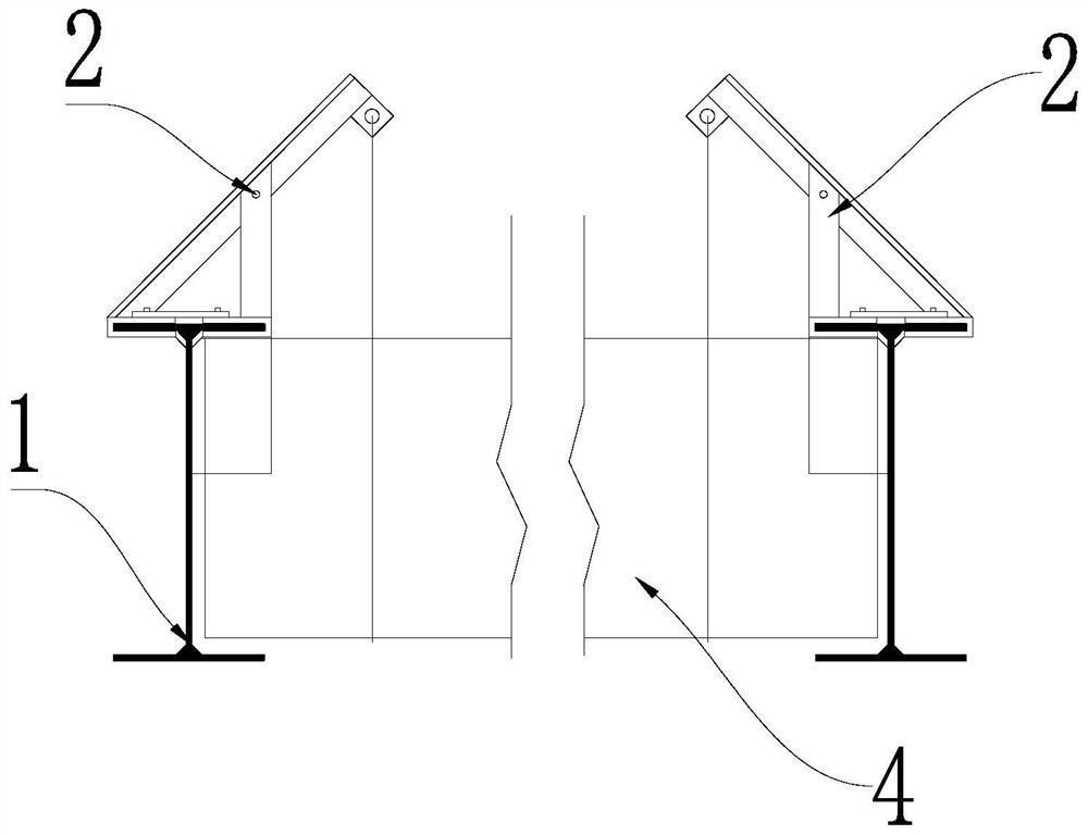
[0027] Embodiment 3: In this embodiment, a fifth threaded hole is provided in the middle of the inclined suspender 21 , and a sixth threaded hole for bolting to the fifth threaded hole is provided on the support rod 24 . Easy to assemble and disassemble. There are multiple hoisting components 2 in this embodiment, and they are arranged around the surrounding profiled steel 1 of the product 4 to be hoisted. When the hoisting component is hoisted to a predetermined position by the crane, the hoisting component can be fixed on the left and right sides of the lifting device 3, and the steel wire rope in the crane can be removed to continue hoisting the next component, which saves time. The lifting device 3 of the present embodiment includes steel wire ropes and / or fixed pulleys. Such as hoisting small products 4 may not install electric hoist, hoisting large products 4 just need to install electric hoist.
PUM
 Abstract
Description
Claims
Application Information
 - R&D Engineer
- R&D Manager
- IP Professional
- Industry Leading Data Capabilities
- Powerful AI technology
- Patent DNA Extraction
Browse by: Latest US Patents, China's latest patents, Technical Efficacy Thesaurus, Application Domain, Technology Topic, Popular Technical Reports.
© 2024 PatSnap. All rights reserved.Legal|Privacy policy|Modern Slavery Act Transparency Statement|Sitemap|About US| Contact US: help@patsnap.com