
Isobaric electric control mechanical filling valve

A filling valve and electronic control technology, applied in packaging, bottle filling, liquid bottling, etc., can solve the problems of waste of resources, short service life, easy damage of filling valve, etc., to eliminate liquid level deviation and prolong service life , the effect of avoiding environmental pollution

Pending Publication Date: 2021-03-30
江苏辉河包装机械有限公司
View PDF0 Cites 0 Cited by
  • Summary
  • Abstract
  • Description
  • Claims
  • Application Information

AI Technical Summary

Problems solved by technology

[0002] The filling valve is an on-off valve that precisely and quantitatively controls the flow rate. It is often used in filling equipment. The existing filling valves all use traditional mechanical filling valves, which are widely used in China because of their low cost and simple maintenance. , but the opening and closing valve, back pressure, exhaust and other actions of the traditional mechanical filling valve are all driven by the friction of mechanical parts. When used in high-speed filling equipment, the mechanical friction action is often not in place, resulting in filling The liquid that enters the container turns over, which eventually leads to a large deviation of the liquid level in the container after filling, and the frequent and rapid mechanical friction during high-speed filling causes the filling valve to be easily damaged and has a short service life; in addition, the current Some filling valves need to use carbon dioxide gas to purge the container after a single filling, and all the purged carbon dioxide gas is discharged to the outside, making it impossible to continue to use, which not only pollutes the environment, but also causes a serious waste of resources , urgently need to be resolved

Method used


Image

  • Isobaric electric control mechanical filling valve
  • Isobaric electric control mechanical filling valve
  • Isobaric electric control mechanical filling valve

Examples


Embodiment Construction

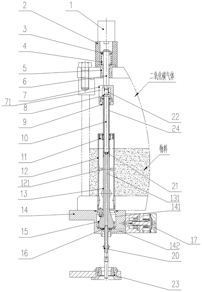
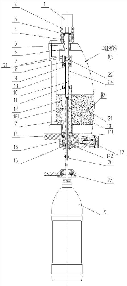
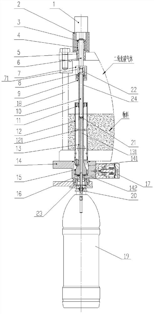
[0019] Such as Figure 1~2 As shown, an isobaric electronically controlled mechanical filling valve includes a valve seat 14, a valve body 12 vertically fixed on the top of the valve seat 14, and a valve core 13 that is vertically interspersed in the valve body 12 and can slide up and down; The top of the valve seat 14 is provided with a valve cavity 141, and a comb-shaped sleeve 15 is embedded in the valve cavity 141. The lower end of the valve core 13 is movably inserted in the comb-shaped sleeve 15 and cooperates with the lower opening of the valve cavity 141. There are vent holes 131 vertically distributed in 13, and a plurality of liquid inlet holes 121 are opened on the outer wall of the valve body 12; it also includes a guide block 11, a sleeve 24, a gasket 16, a gas return pipe 20 and a diaphragm valve 17; The sleeve 24 is vertically and concentrically fixed on the upper end of the valve core 13, the guide block 11 is sheathed and fixed on the upper end of the valve co...


PUM


Abstract

The invention relates to an isobaric electric control mechanical filling valve. The isobaric electric control mechanical filling valve comprises a valve seat, a valve body vertically fixed to the topof the valve seat, and a valve element vertically inserted into the valve body in a penetrating mode and capable of sliding up and down; a valve cavity is formed in the top of the valve seat, a comb-shaped sleeve is embedded in the valve cavity, and the lower end of the valve element is movably inserted into the comb-shaped sleeve and matched with an opening in the lower end of the valve cavity; the isobaric electric control mechanical filling valve further comprises a guide block, a casing pipe, a sealing gasket, a gas return pipe and diaphragm valves; the casing pipe is vertically and concentrically fixed to the upper end of the valve element, the guide block is fixed to the upper end of the valve element in a sleeving mode and movably embedded in the valve body, and the sealing gasket is embedded in the outer side of the lower end of the valve element in a sleeving mode; and the gas return pipe is vertically inserted into an opening in the lower end of a vent hole. According to theisobaric electric control mechanical filling valve, the liquid level deviation in a filled container is effectively eliminated, and the service life is prolonged; and besides, carbon dioxide gas for purging is completely recycled by virtue of the two diaphragm valves for cycle use, so that the environmental pollution is avoided, and resources are also effectively saved.

Description

technical field [0001] The invention relates to an equal pressure electronically controlled mechanical filling valve. Background technique [0002] The filling valve is an on-off valve that precisely and quantitatively controls the flow rate. It is often used in filling equipment. The existing filling valves all use traditional mechanical filling valves, which are widely used in China because of their low cost and simple maintenance. , but the opening and closing valve, back pressure, exhaust and other actions of the traditional mechanical filling valve are all driven by the friction of mechanical parts. When used in high-speed filling equipment, the mechanical friction action is often not in place, resulting in filling The liquid that enters the container turns over, which eventually leads to a large deviation of the liquid level in the container after filling, and the frequent and rapid mechanical friction during high-speed filling causes the filling valve to be easily dam...

Claims


Application Information

Patent Timeline
Patent Type & Authority Applications(China)
IPC IPC(8): B67C3/26
CPCB67C3/26B67C2003/2602B67C2003/2671
Inventor 唐志华唐光海王晶张捷袁丽芳李圣兵
Owner 江苏辉河包装机械有限公司
Learn More