Tubular connecting piece, heat-preservation outer formwork cast-in-place concrete wall and wall construction method

A technology for concrete walls and connectors, which is applied in the direction of walls, building components, buildings, etc., can solve the problems of lack of thermal insulation external formwork support and positioning functions.

Pending Publication Date: 2021-03-30
山东赛昌新型材料有限公司
View PDF0 Cites 0 Cited by
  • Summary
  • Abstract
  • Description
  • Claims
  • Application Information

AI Technical Summary

Problems solved by technology

[0003] The invention provides a tubular connector, which solves the problem in the prior art that the pull bolt casing does not have the function of supporting and positioning the thermal insulation outer formwork

Method used


Image

  • Tubular connecting piece, heat-preservation outer formwork cast-in-place concrete wall and wall construction method
  • Tubular connecting piece, heat-preservation outer formwork cast-in-place concrete wall and wall construction method

Examples


Embodiment 1

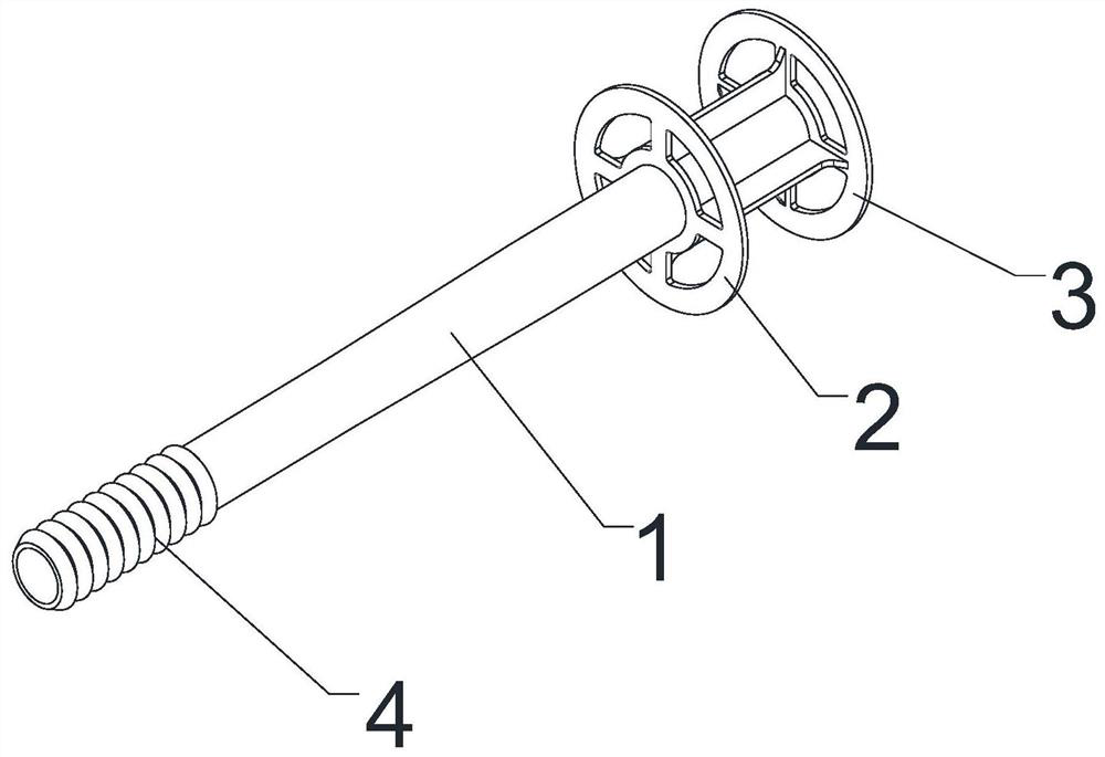
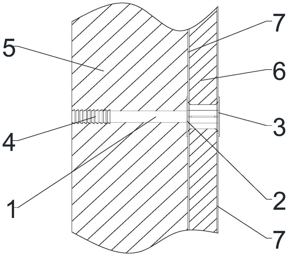
[0036] Such as figure 1 As shown, the tubular connector includes a tube body 1, the axial channel of the tube body 1 runs through the tube body 1 to form openings at both ends of the tube body 1, and the outer wall of the tube body 1 is provided with a first limiting piece 2 and a second limiting piece. The positioning piece 3 and the second limiting piece 3 are located at one end of the tube body 1 . When the tubular connector of the present invention is in use, the first limiting piece 2 and the second limiting piece 3 are located on both sides of the thermal insulation outer formwork 6 to realize the positioning of the thermal insulation outer formwork 6, and one end of the pipe body 1 abuts against the inner formwork , to realize the support of the inner formwork, and after tightening the inner formwork and the heat preservation outer formwork 6 by the pulling bolts, the fixing of the inner formwork and the heat preservation outer formwork 6 is realized. The second limiti...

Embodiment 2

[0046] The difference between this embodiment and embodiment 1 is that the first limiting piece 2 is fixedly connected or integrally formed with the tube body 1 , and the second limiting piece 3 is detachably connected with the tube body 1 . After the pipe body 1 passes through the thermal insulation outer formwork 6, the second limiting piece 3 is installed on the pipe body 1, and the second limiting piece 3 and the tubular body 1 are detachably connected to facilitate the assembly of the tubular connector and the thermal insulation outer formwork 6. Threads are provided on the outer wall of the pipe body 1, and the first limiting piece 2 is threadedly connected with the pipe body 1; The body 1 is detachably connected; or the outer wall of the tube body 1 is provided with a barb structure, and the first limiting piece 2 is connected with the tube body 1 through the barb structure.

[0047] The wall construction method comprises the following steps:

[0048] Step 1, opening a...

Embodiment 3

[0054] The difference between this embodiment and embodiment 1 is that both the first limiting piece 2 and the second limiting piece 3 are detachably connected to the tube body 1 .

[0055] The wall construction method comprises the following steps:

[0056] Step 1, opening a through hole on the heat preservation outer formwork 6, and then standing the heat preservation outer formwork 6 on the outside of the reinforcement frame;

[0057] Step 2, remove the first limiting piece 2 / second limiting piece 3, pass the tube body 1 through the through hole, and then install the first limiting piece 2 / second limiting piece 3 on the tube body 1, Make the first spacer 2 and the second spacer 3 lean against the thermal insulation outer template 6;

[0058] Step 3, supporting the inner formwork, passing the tension bolts through the inner formwork and the pipe body 1, and tightening the tension bolts;

[0059] Step 4, pouring concrete between the inner formwork and the thermal insulation...


PUM


Abstract

The invention relates to the field of building construction, and solves the problem that in the prior art, a split bolt sleeve does not have the supporting and positioning effects on a heat-preservation outer formwork. A tubular connecting piece comprises a tube body, an axial channel of the tube body penetrates through the tube body to form openings in the two ends of the tube body, a first limiting piece and a second limiting piece are arranged on the outer side wall of the tube body, and the second limiting piece is located at one end of the tube body. When the tubular connecting piece is used, the first limiting piece and the second limiting piece are located on the two sides of the heat-preservation outer formwork, positioning of the heat-preservation outer formwork is achieved, one end of the tube body abuts against the inner formwork, supporting of the inner formwork is achieved, and after the inner formwork and the heat-preservation outer formwork are tensioned through the split bolt, the inner formwork and the heat-preservation outer formwork are fixed. A heat-preservation outer formwork cast-in-place concrete wall comprises a wall body, a heat-preservation outer formworkand the tubular connecting piece, the tube body penetrates through the wall body and the heat-preservation outer formwork, and the first limiting piece and the second limiting piece are located on thetwo sides of the heat-preservation outer formwork respectively.

Description

technical field [0001] The invention relates to the field of building construction, in particular to a tubular connector, a cast-in-situ concrete wall with an external thermal insulation formwork and a construction method for the wall. Background technique [0002] The non-demolition thermal insulation external formwork means that the thermal insulation external formwork is used as the formwork on the outer wall side of the wall, and the conventional formwork is used on the inner wall side of the wall. The pull bolt casing does not have the function of supporting and positioning the thermal insulation outer formwork, so the conventional formwork and the thermal insulation outer formwork also need to be supported by connectors to realize the fixation of the conventional formwork and the thermal insulation outer formwork. After the pouring is completed, the pull bolts and conventional formwork are removed, and the thermal insulation outer formwork and the wall form an integrat...

Claims


Application Information

Patent Timeline
Patent Type & Authority Applications(China)
IPC IPC(8): E04B2/86
CPCE04B2/8647
Inventor 刘文起郑继成
Owner 山东赛昌新型材料有限公司
Why Eureka
Try Eureka