A rubber bracket
A kind of bracket and glue blocking technology, which can be applied to devices and coatings that apply liquid to the surface. It can solve the problems of easy overflow of colloid and adhesion to the outer surface of the bracket body, etc., so as to improve shift output and reduce capital investment. , Improve the effect of assembly accuracy
- Summary
- Abstract
- Description
- Claims
- Application Information
AI Technical Summary
Problems solved by technology
Method used
Image
Examples
Embodiment 1
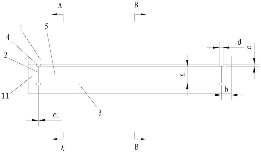
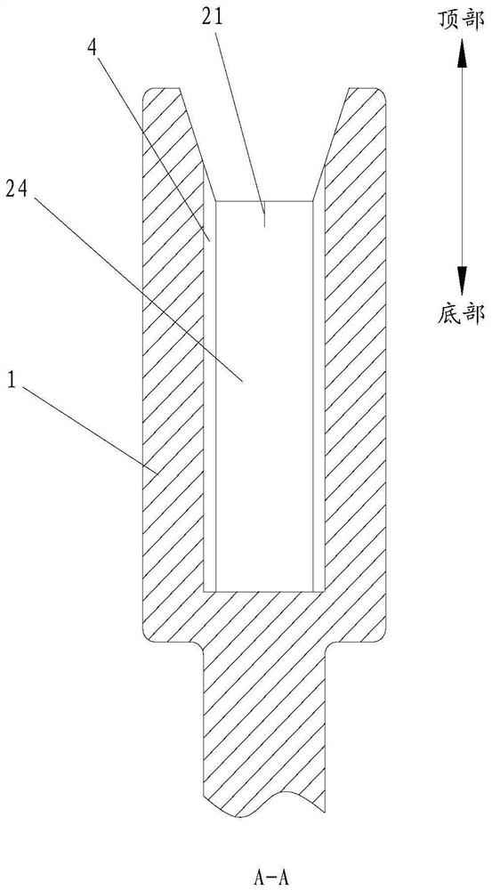
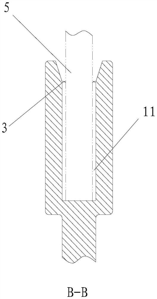
[0070] Please refer to Figure 1-Figure 5 and Figure 14-Figure 15 , a rubber blocking bracket, including a bracket body 1, a plurality of first rubber blocking parts 2, a plurality of second rubber blocking parts 3 and a plurality of supporting parts 4;
[0071] The top of the bracket body 1 is provided with an installation groove 11 for holding the colloid to bond the glass 5;
[0072] The inner walls on both sides of the installation groove 11 are respectively equipped with a plurality of supporting parts 4;
[0073] A plurality of first rubber stoppers 2 are correspondingly installed between two opposite supporting parts 4, and one end of the first rubber stoppers 2 is provided with a cutout 21 for installing glass 5;
[0074] A plurality of second rubber blocking members 3 are arranged oppositely on two oppositely arranged side walls of the installation groove 11 .
[0075] Preferably, there are two first rubber stoppers 2 and second rubber stoppers 3, and four support...
Embodiment 2
[0091] The difference between this embodiment and the first embodiment is that the second structure of the first rubber stop is defined.
[0092] refer to Figure 6-Figure 11 The two oppositely arranged side walls of the bracket body 1 are respectively provided with an assembly groove 12 that is isosceles trapezoidal when viewed from above;
[0093] refer to Figure 9 A V-shaped groove 22 is opened on the side of the first rubber blocking member 2 away from the second rubber blocking member 3 ; the notch 21 is opened in the V-shaped groove 22 .
[0094] refer to Figure 6-Figure 9 , the first glue stopper 2 includes a glued film 23 and two pieces of glued film 24; , and the other end is pressed against the second rubber blocking member 3; There is always a gap between the adhesive film 23 and the second rubber blocking member 3, so that the PU glue overflows evenly from the gap between the adhesive film 23 and the bracket body 1, and forms a strip-shaped adhesive strip 6 e...
Embodiment 3
[0105] The difference between this embodiment and the second embodiment is that the third structure of the first rubber stop is defined.
[0106] refer to Figure 12-Figure 15 The two oppositely arranged side walls of the bracket body 1 are respectively provided with an assembly groove 12 that is isosceles trapezoidal when viewed from above;
[0107] refer to Figure 12 and Figure 13 , the first rubber blocking member 2 includes a rubber blocking film 24 .
[0108] refer to Figure 12 and Figure 13 , the first rubber blocking member 2 is planar and vertically arranged between the two supporting parts 4 .
[0109] refer to Figure 12 and Figure 13 , the first rubber blocking member 2 is also provided with a saw-toothed notch 25 ;
[0110] Optionally, the height L of the notch 25 3 2mm~10mm, width W 3 2mm to 5mm.
[0111] The rubber blocking film 24 with serrated notches can also be manufactured by injection molding or extrusion plus rolling notches, and then assem...
PUM
 Abstract
Description
Claims
Application Information
 - R&D
- Intellectual Property
- Life Sciences
- Materials
- Tech Scout
- Unparalleled Data Quality
- Higher Quality Content
- 60% Fewer Hallucinations
Browse by: Latest US Patents, China's latest patents, Technical Efficacy Thesaurus, Application Domain, Technology Topic, Popular Technical Reports.
© 2025 PatSnap. All rights reserved.Legal|Privacy policy|Modern Slavery Act Transparency Statement|Sitemap|About US| Contact US: help@patsnap.com


