Cut-off device for steel pipe machining and capable of conducting waste reduction treatment

A cutting device and steel pipe technology, which is applied in the field of steel pipe processing, can solve the problems of reducing the accuracy of steel pipes, inconvenient splashing sparks and debris blocking protection, inconvenient steel pipe limit and fixation, etc., to achieve the effect of improving stability

Inactive Publication Date: 2021-04-02
芜湖博威机械制造有限公司
View PDF9 Cites 0 Cited by
  • Summary
  • Abstract
  • Description
  • Claims
  • Application Information

AI Technical Summary

Problems solved by technology

[0007] The object of the present invention is to provide a cut-off device for steel pipe processing that can reduce the amount of waste, so as to solve the problem that the existing cut-off device proposed in the background technology is not convenient to play a good limit on the steel pipe when cutting the steel pipe Fixing effect, which leads to the problem that the steel pipe is prone to shift and shake during processing, which greatly reduces the accuracy of the steel pipe when it is cut. Sparks and debris play a blocking and protective role, causing flying sparks to easily cause unnecessary injuries to surrounding workers, thereby reducing the practicability of the cutting device itself

Method used


Image

  • Cut-off device for steel pipe machining and capable of conducting waste reduction treatment
  • Cut-off device for steel pipe machining and capable of conducting waste reduction treatment
  • Cut-off device for steel pipe machining and capable of conducting waste reduction treatment

Examples


Embodiment Construction

[0025] The following will clearly and completely describe the technical solutions in the embodiments of the present invention with reference to the accompanying drawings in the embodiments of the present invention. Obviously, the described embodiments are only some, not all, embodiments of the present invention. Based on the embodiments of the present invention, all other embodiments obtained by persons of ordinary skill in the art without making creative efforts belong to the protection scope of the present invention.

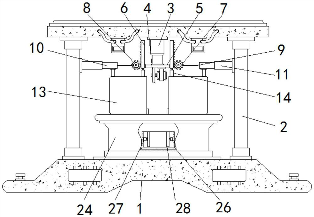
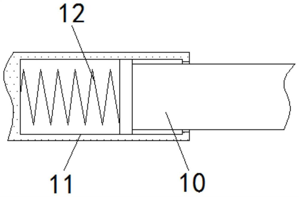
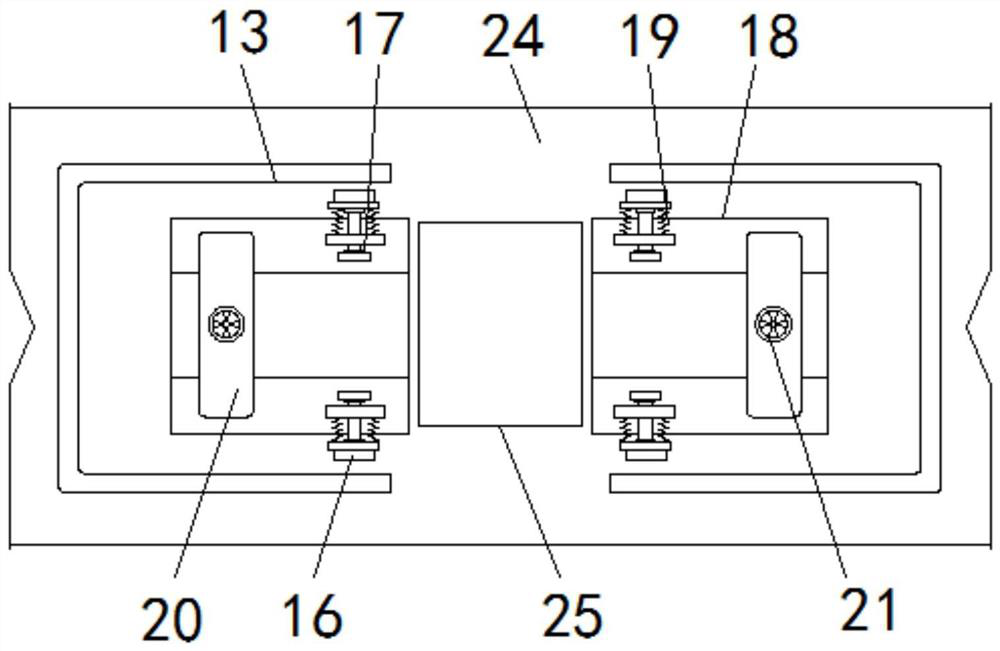
[0026] see Figure 1-6 , the present invention provides a technical solution: a cut-off device for steel pipe processing that can reduce the amount of waste, including a base 1, a support frame 2, an electric push rod 3, a transverse plate 4, a cutting blade 5, a rack 6, a round Shaped gear 7, central rod 8, traction rope 9, pull rod 10, guide column 11, compression spring 12, protective cover 13, fixed frame 14, pulley 15, pressure block 16, positioning rod 1...


PUM


Abstract

The invention discloses a cut-off device for steel pipe machining and capable of conducting waste reduction treatment. The cut-off device comprises a base, a supporting frame, an electric push rod, acutting blade, a workbench and an electric telescopic rod, the supporting frame is fixedly installed at the upper end of the base, and the electric push rod is installed below the middle of the upperend of the supporting frame; and the outer end of a traction rope is fixedly installed at the inner end of a pull rod, the outer end of the pull rod is installed in a guide column, a placing block isinstalled on the inner side of a protective cover, a connecting frame is fixedly installed on the placing block, the placing block is fixedly installed at the upper end of the workbench, a dischargingopening is formed in the middle of the workbench, and a collecting chamber is mounted at the lower end of the discharging opening. According to the cut-off device for steel pipe machining and capableof conducting waste reduction treatment, a good limiting and fixing effect can be achieved when a steel pipe is cut off, the possibility that the steel pipe deviates and shakes is reduced, and meanwhile sparks generated in the machining process can be blocked and protected.

Description

technical field [0001] The invention relates to the technical field of steel pipe processing, in particular to a cutting device for steel pipe processing that can reduce waste materials. Background technique [0002] The steel pipe is a pipe with a hollow cross-section whose length is much greater than the diameter or circumference. When in use, the steel pipe can be divided into several categories according to the shape of the cross-section, such as circular, square and rectangular. The steel pipe can transport fluid, exchange heat and Manufacture of mechanical parts, so steel pipes are widely used in various fields. In order to meet the customer's steel pipe size requirements during steel pipe production, a cutting device is usually used. Through the cutting device, the steel pipe can be cut into various sizes. However, most of the general cut-off devices will compress the volume of the waste generated during the cut-off, so as to achieve the purpose of waste reduction tre...

Claims


Application Information

Patent Timeline
Patent Type & Authority Applications(China)
IPC IPC(8): B23D21/00B23D33/00B23D33/02B23Q11/08
CPCB23D21/00B23D33/00B23D33/02B23Q11/08
Inventor 卢祖杰
Owner 芜湖博威机械制造有限公司
Why Eureka
Try Eureka