Precision die for chip shell

A technology for precision molds and chip casings, applied in the field of precision molds for chip casings, can solve problems such as unreasonable layout, uneven eccentric wall thickness, and insufficient core pulling, so as to solve the problem of large mold structure, good market application value, and use. handy effect

Active Publication Date: 2021-04-02
天鑫精工科技(威海)有限公司
View PDF2 Cites 0 Cited by
  • Summary
  • Abstract
  • Description
  • Claims
  • Application Information

AI Technical Summary

Problems solved by technology

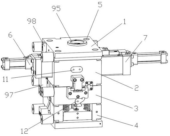
In the current market, the slanted holes of products continue to diversify. When injecting parts with multi-directional slanted holes, if there are buckles inside the workpiece, a backhoe is required, which will cause the entire mold structure to be huge, especially when processing small-sized workpieces. It is difficult to meet the structural needs; for a long time, the backhoe of the slider and the layout of the inclined guide pillars have interfered with each other, resulting in flashes on the plastic parts, uneven eccentric wall thickness of the size, and core-pulling is prone to occur due to the limitation of the core-pulling angle and structure Not in place, not reset to the end, causing bruises, production accuracy is difficult to control and other defects, and ideal qualified products cannot be obtained; to solve this problem, this application provides a multiple oblique core-pulling and horizontal core-pulling plus backhoe Mechanism-integrated mold perfectly solves the problems of huge mold structure and unreasonable layout of various mechanisms

Method used


Image

  • Precision die for chip shell
  • Precision die for chip shell
  • Precision die for chip shell

Examples


Embodiment Construction

[0026] In order to facilitate the understanding of the present invention, the present invention will be described in more detail below in conjunction with the accompanying drawings and specific embodiments. Preferred embodiments of the invention are shown in the accompanying drawings. However, the present invention can be implemented in many different forms and is not limited to the embodiments described in this specification. On the contrary, these embodiments are provided to make the understanding of the disclosure of the present invention more thorough and comprehensive.

[0027] It should be noted that when an element is referred to as being “fixed” to another element, it can be directly on the other element or there can also be an intervening element. When an element is referred to as being "connected to" another element, it can be directly connected to the other element or intervening elements may also be present. The terms "vertical", "horizontal", "left", "right", "f...


PUM


Abstract

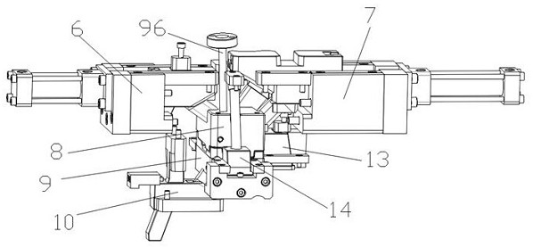
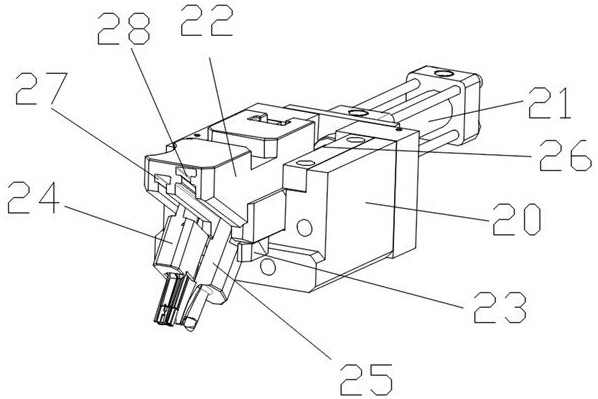
The invention relates to the field of dies, in particular to a precision die for a chip shell. The precision die for the chip shell comprises a top plate, an upper die, a lower die and a base which are sequentially connected through guide columns from top to bottom, wherein a first inclined core-pulling mechanism and a second inclined core-pulling mechanism are respectively arranged on the left side and the right side of the upper die; a third inclined core-pulling mechanism is arranged on the left side of the base; the front end of the first inclined core-pulling mechanism extends into a cavity from the left side of the top of an upper die core; the front end of the second inclined core-pulling mechanism extends into the cavity from the right side of the top of the upper die core; the front end of the third inclined core-pulling mechanism extends into the cavity from the left side of the bottom of a lower die core; a first cooling mechanism and a second cooling mechanism are respectively arranged on the front side face of the upper die and the front side face of the lower die; a backhoe mechanism is arranged on the right side of the top of the lower die; and horizontal core-pulling mechanisms are oppositely arranged on the left side and the right side between the upper die and the lower die respectively. According to the precision die for the chip shell provided by the invention, the integration of multiple inclined core-pulling, horizontal core-pulling and backhoe mechanisms is realized, the problems of huge die structure and unreasonable layout of each mechanism are solved, and a good market application value is achieved.

Description

technical field [0001] The invention relates to the field of molds, in particular to a precision mold used for chip shells. Background technique [0002] Injection molds are commonly used molds in the field of existing product manufacturing, and their usual structures include two-plate molds, three-plate molds, I-shaped molds and straight body molds. In the production of injection molding products, the step of core pulling is often involved, and the core pulling methods vary widely, one of which is oblique hole core pulling. In the current market, the slanted holes of products continue to diversify. When injecting parts with multi-directional slanted holes, if there are buckles inside the workpiece, a backhoe is required, which will cause the entire mold structure to be huge, especially when processing small-sized workpieces. It is difficult to meet the structural needs; for a long time, the backhoe of the slider and the layout of the inclined guide pillars have interfered ...

Claims


Application Information

Patent Timeline
Patent Type & Authority Applications(China)
IPC IPC(8): B29C45/33B29C45/73
CPCB29C45/33B29C45/73
Inventor 姚金才陈宇朱超群
Owner 天鑫精工科技(威海)有限公司
Why Eureka
Try Eureka