
Corner hanging type air conditioner

An air conditioner and corner-mounted technology, which is applied in the field of corner-mounted air conditioners, can solve the problems of easy blowing of cold air, inability to solve the problem of heating comfort, the problem of large circulation of hot air landing on the ground, and the poor uniformity of the air-concentrated room. , to achieve the effect of improving human comfort, enriching air supply forms, and improving heat exchange effect.

Inactive Publication Date: 2021-04-02
GREE ELECTRIC APPLIANCES INC
View PDF6 Cites 1 Cited by
  • Summary
  • Abstract
  • Description
  • Claims
  • Application Information

AI Technical Summary

Problems solved by technology

[0002] The air duct structure of conventional mainstream indoor air conditioners is composed of a single cross-flow fan, a single air inlet, a single air outlet, and a single-row or double-row folded evaporator, and the air supply in cooling and heating conditions is realized through the air deflector. This traditional air supply method has the problems of single air supply form, hot air does not fall to the ground, cold air is easy to blow people, poor uniformity of air flow in the room, and insufficient air volume
[0003] The patent CN208566888U combines the fresh air and the air conditioner and installs it in the corner, but still adopts the air inlet and outlet methods of the conventional wall-mounted machine, which cannot form multiple air outlets for air supply, nor can it form a large circulation of airflow organization, and the comfort problem is still prominent; patent CN211316335U The conventional wall-mounted unit is designed upside down, and the air outlet is set on the upper end of the air conditioner, which is beneficial to cooling, but it cannot solve the problem of heating comfort, hot air landing, and large circulation of air circulation

Method used


Image

  • Corner hanging type air conditioner
  • Corner hanging type air conditioner
  • Corner hanging type air conditioner

Examples


Embodiment 1

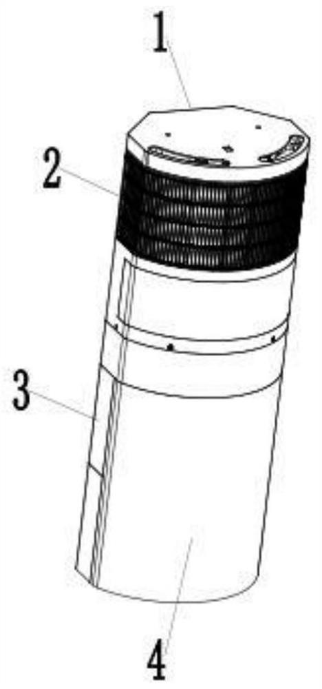
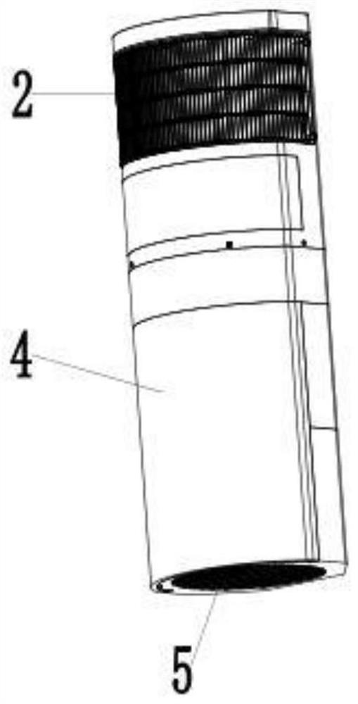
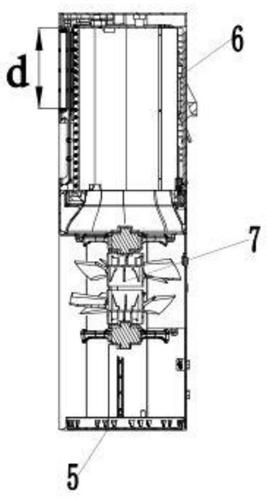
[0027] like Figure 1-3 As shown, a corner-mounted air conditioner includes a casing, a heat exchanger 6 and a counter-rotating fan 7, the upper front side of the casing is provided with an upper wind plate 2, and the bottom of the casing is provided with a lower wind plate 5 , the inside of the casing is provided with a heat exchanger 6 and a counter-cyclone fan 7, and the heat exchanger 6 is located above the counter-cyclone fan 7, as Image 6 As shown, the heat exchanger 6 is an open ring structure.

[0028] like Figure 4 , 5 As shown, the casing includes a front panel 4, a side panel 3 and a rear panel 9, side panels 3 are provided on both sides of the front panel 4, and a fixing plate 8 is provided at the end of the side panel 3 away from the front panel 4 , the fixed plates 8 on both sides are connected by the rear panel 9, the upper end of the upper wind plate 2 is connected with the front panel 4, the two ends of the upper wind plate 2 are connected with the fixed ...

Embodiment 2

[0039] like Figure 1-6 As shown, a corner-mounted air conditioner includes a casing, a heat exchanger 6 and a counter-rotating fan 7, the upper front side of the casing is provided with an upper wind plate 2, and the bottom of the casing is provided with a lower wind plate 5 , the interior of the casing is provided with a heat exchanger 6 and a counter-cyclone fan 7, the heat exchanger 6 is located above the counter-cyclone fan 7, and the heat exchanger 6 is an open ring structure.

[0040] The casing includes a front panel 4, a side panel 3 and a rear panel 9. Side panels 3 are provided on both sides of the front panel 4, and a fixing plate 8 is provided at an end of the side panel 3 away from the front panel 4. The fixed plate 8 is connected through the rear panel 9, the upper end of the windward plate 2 is connected with the upper end of the front panel 4, the two ends of the upper windward plate 2 are connected with the fixed plate 8, and the upper end cover of the upper ...

Embodiment 3

[0048] like Figure 1-6 As shown, a corner-mounted air conditioner includes a casing, a heat exchanger 6 and a counter-rotating fan 7, the upper front side of the casing is provided with an upper wind plate 2, and the bottom of the casing is provided with a lower wind plate 5 , the interior of the casing is provided with a heat exchanger 6 and a counter-cyclone fan 7, the heat exchanger 6 is located above the counter-cyclone fan 7, and the heat exchanger 6 is an open ring structure.

[0049] The casing includes a front panel 4, a side panel 3 and a rear panel 9. Side panels 3 are provided on both sides of the front panel 4, and a fixing plate 8 is provided at an end of the side panel 3 away from the front panel 4. The fixed plate 8 is connected through the rear panel 9, the upper end of the windward plate 2 is connected with the upper end of the front panel 4, the two ends of the upper windward plate 2 are connected with the fixed plate 8, and the upper end cover of the upper ...


PUM


Abstract

The invention discloses a corner hanging type air conditioner. The conditioner comprises a machine shell, a heat exchanger and a counter-rotating fan, wherein an upper air plate is arranged on the front side of the upper end of the machine shell, a lower air plate is arranged at the bottom of the machine shell, the heat exchanger and the counter-rotating fan are arranged inside the machine shell,the heat exchanger is located above the counter-rotating fan, and the heat exchanger is of an open annular structure. According to the conditioner, two inclined side faces of the cylindrical shell andthe wall face of a wall corner are mounted in a matched mode, so that main flow passing through an air opening flows towards the opposite angles of a room, a main heat exchange area of the room is changed, and the heat exchange effect is improved; the counter-rotating fan, an upper air opening and a lower air opening are arranged and combined with angular installation to form airflow organizationlarge circulation of diagonal areas of the room, refrigerating and heating can form different temperature layers correspondingly, and the comfort of a human body is improved; and the counter-rotatingfan is combined with the upper and lower air ports to form multi-directional air supply, and the air supply forms are rich.

Description

technical field [0001] The invention relates to the technical field of air conditioners, in particular to a corner-mounted air conditioner. Background technique [0002] The air duct structure of conventional mainstream indoor air conditioners is composed of a single cross-flow fan, a single air inlet, a single air outlet, and a single-row or double-row folded evaporator, and the air supply in cooling and heating conditions is realized through the air deflector. This traditional air supply method has the problems of single air supply form, hot air does not fall to the ground, cold air is easy to blow people, poor uniformity of airflow in concentrated rooms, and insufficient air volume. [0003] The patent CN208566888U combines the fresh air and the air conditioner and installs it in the corner, but still adopts the air inlet and outlet methods of the conventional wall-mounted machine, which cannot form multiple air outlets for air supply, nor can it form a large circulation ...

Claims


Application Information

Patent Timeline
IPC IPC(8): F24F1/0014F24F1/0018F24F1/0063F24F1/0057
CPCF24F1/0014F24F1/0018F24F1/0057F24F1/0063
Inventor 黄鑫李树云高智强田雅颂陈志伟陈英强
Owner GREE ELECTRIC APPLIANCES INC
Learn More