Optical cable traction machine suitable for optical cables of different specifications and capable of automatically compressing

A technology of traction machine and optical cable, which is applied in the direction of optical fiber/cable installation, etc. It can solve the problems of easily damaged optical cable, difficulty, and low versatility, and achieve the effect of eliminating the need to adjust pressure, ensuring pressure, and avoiding slipping

Inactive Publication Date: 2021-04-02
成都沁域网络科技有限公司
View PDF0 Cites 1 Cited by
  • Summary
  • Abstract
  • Description
  • Claims
  • Application Information

AI Technical Summary

Problems solved by technology

[0002] At present, when the optical cable is laid in two adjacent optical cable wells, it is necessary to use the optical cable puller, but most of the current optical cable pullers are only suitable for one type of optical cable, so the versatility is low, but currently applicable to multiple specifications When the optical cable pulling machine is in use, it is necessary to manually adjust the pressure of the machine on the optical cable, which is relatively cumbersome, and because the optical cable has certain requirements on the pressure, too small will easily cause slippage, and too large will easily damage the optical cable, so manual adjustment Appropriate pressure has certain difficulties and risks

Method used


Image

  • Optical cable traction machine suitable for optical cables of different specifications and capable of automatically compressing
  • Optical cable traction machine suitable for optical cables of different specifications and capable of automatically compressing
  • Optical cable traction machine suitable for optical cables of different specifications and capable of automatically compressing

Examples


Embodiment Construction

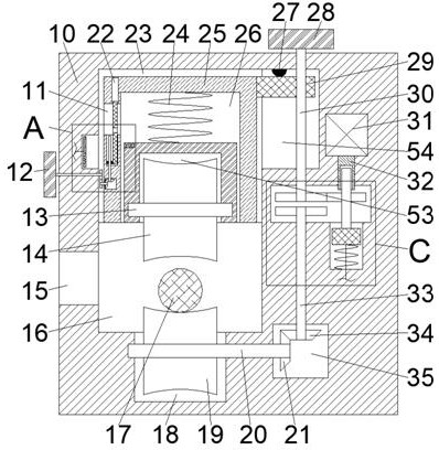
[0016] Combine below Figure 1-4 The present invention is described in detail, wherein, for the convenience of description, the orientations mentioned below are defined as follows: figure 1 The up, down, left, right, front and back directions of the projection relationship itself are the same.

[0017] An optical cable pulling machine that is suitable for optical cables of different specifications and can be automatically compressed, as described in conjunction with accompanying drawings 1-4, includes a main body box 10, and a main drawing cavity 16 that runs through the front and back is provided in the main body box 10. The left end wall of the traction cavity 16 is connected with an optical cable inlet cavity 15 with an opening to the left and through front and rear. The upper end wall of the main traction cavity 16 is connected with a main compression block cavity 23. Friction roller cavity 18, the upper end of the right end wall of the main compression block cavity 23 is...


PUM


Abstract

The invention relates to the related field of optical cables, and discloses an optical cable traction machine suitable for optical cables of different specifications and capable of automatically compressing. The optical cable traction machine comprises a main body box, a front-back through main traction cavity is arranged in the main body box, the left end wall of the main traction cavity is communicated with an optical cable inlet cavity with a leftward opening, and the upper end wall of the main traction cavity is communicated with a main compressing block cavity, the lower end wall of the main traction cavity is communicated with a lower friction roller cavity; according to the device, proper pressure values of cables of different specifications can be set in a user-defined mode throughthe pressure adjusting knob, the upper friction roller capable of moving downwards is matched with the pressing spring at the same time, and thus the device can automatically compress the optical cable according to the pressure values set in advance; on one hand, the trouble of manually and frequently adjusting the pressure is saved, on the other hand, the pressure borne by the optical cable is ensured to be constant, and slipping caused by too small pressure or damage to the optical cable due to too large pressure is avoided.

Description

technical field [0001] The invention relates to the field of optical cables, in particular to an optical cable pulling machine which is suitable for optical cables of different specifications and can be automatically pressed. Background technique [0002] At present, when the optical cable is laid in two adjacent optical cable wells, it is necessary to use the optical cable puller, but most of the current optical cable pullers are only suitable for one type of optical cable, so the versatility is low, but currently applicable to multiple specifications When the optical cable pulling machine is in use, it is necessary to manually adjust the pressure of the machine on the optical cable, which is relatively cumbersome, and because the optical cable has certain requirements on the pressure, too small will easily cause slippage, and too large will easily damage the optical cable, so manual adjustment Appropriate pressure has certain difficulties and risks. Contents of the inven...

Claims


Application Information

Patent Timeline
Patent Type & Authority Applications(China)
IPC IPC(8): G02B6/54
CPCG02B6/54
Inventor 徐强
Owner 成都沁域网络科技有限公司
Why Eureka
Try Eureka