
Optimized structure of rolling tool

A technology for optimizing structure and tooling, applied in the direction of connecting components, material gluing, mechanical equipment, etc., can solve the problems of wrist influence, fit effect and pass rate decline, wrist soreness, etc., to increase firmness, reduce labor consumption, The effect of increasing diversity

Pending Publication Date: 2019-12-13
SEKSUN TECH SUZHOU
View PDF0 Cites 0 Cited by
  • Summary
  • Abstract
  • Description
  • Claims
  • Application Information

AI Technical Summary

Problems solved by technology

After working for a period of time, physical exertion, mental fatigue, fit effect and pass rate will decrease to a certain extent; and after a day of work, the wrists of employees are prone to soreness, and working for a long time will have a certain impact on the wrist

Method used


Image

  • Optimized structure of rolling tool
  • Optimized structure of rolling tool
  • Optimized structure of rolling tool

Examples


Embodiment

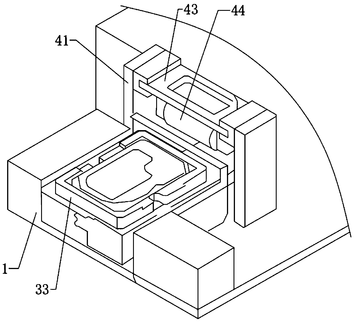
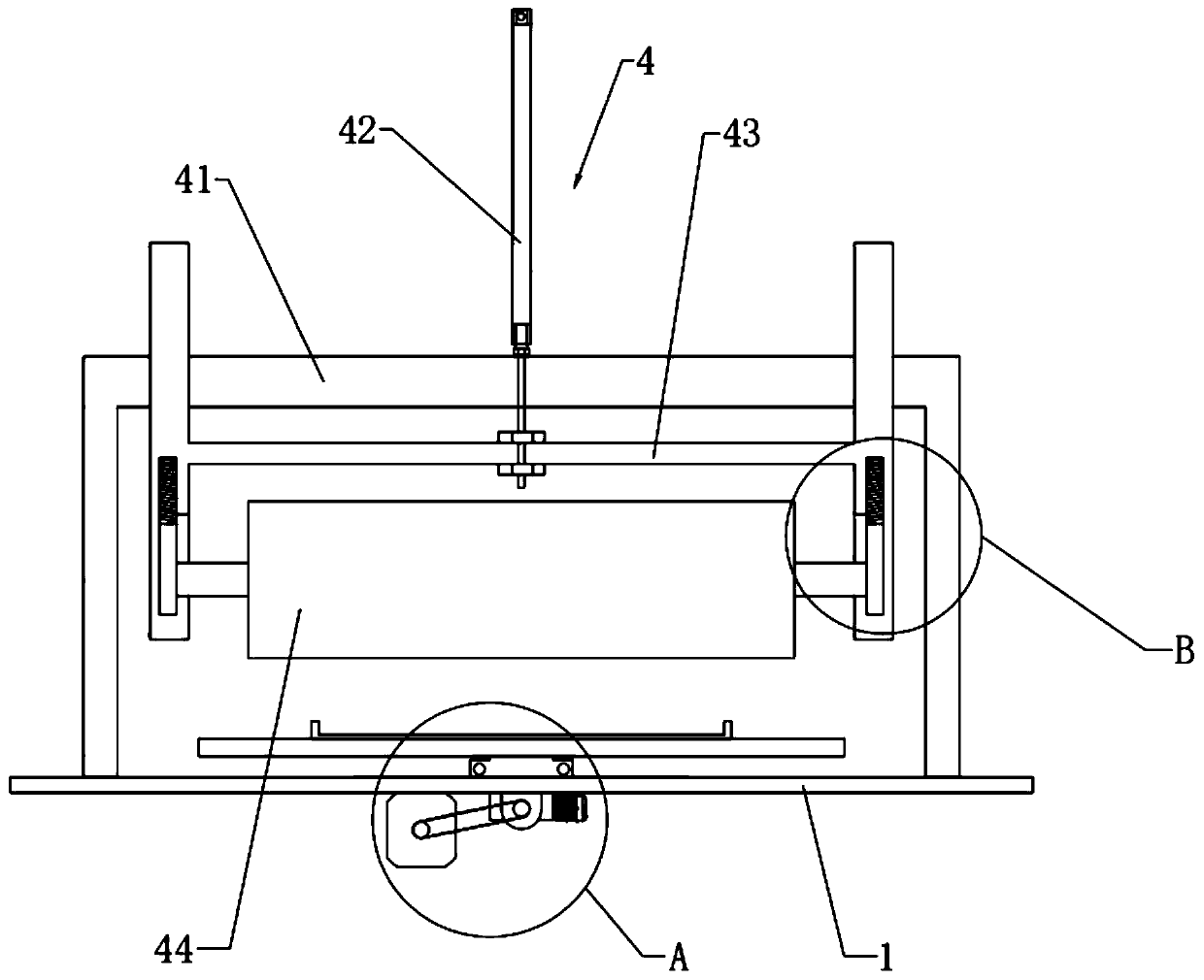
[0022] Example: such as figure 1 and figure 2 As shown, the optimized structure of the rolling tooling includes a machine 1 on which a driving device 2 , a holding device 3 and a rolling device 4 are arranged.

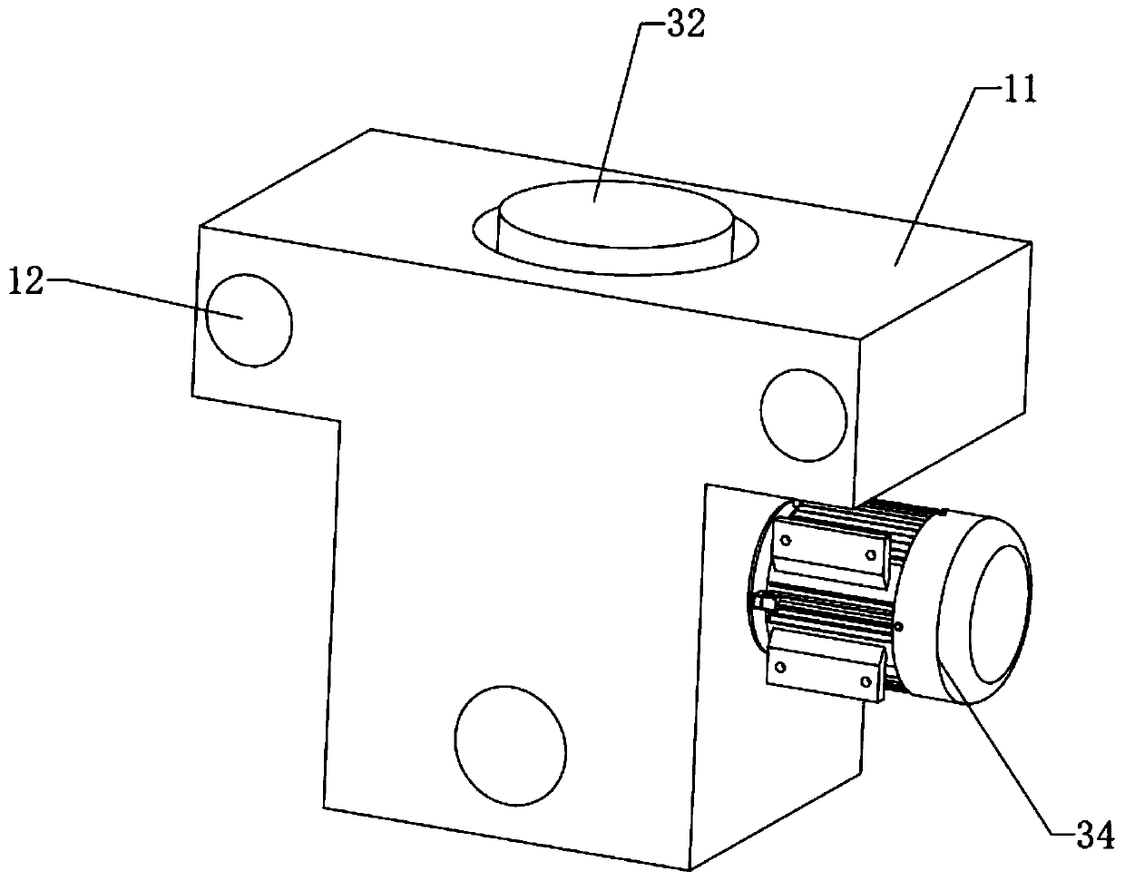
[0023] like figure 2 and Figure 5 As shown, the driving device 2 includes a driving motor 21 fixed on the bottom side of the machine platform 1, the rotating shaft of the driving motor 21 is arranged in the front and rear directions, and two screw seats are fixedly connected to the front and rear sides of the bottom of the machine platform 1, and the two screw seats have a common A driving screw rod 22 is connected in rotation, a belt 23 is provided between the driving motor 21 rotating shaft and the driving screw rod 22, and the inner ring of the belt 23 is enclosed within the peripheral wall of the rotating shaft of the driving motor 21 and the peripheral wall of the driving screw rod 22 simultaneously.

[0024] like image 3 and Figure 5 As shown, the holdi...


PUM


Abstract

The invention discloses an optimized structure of a rolling tool. The optimized structure of the rolling tool comprises a machine table, wherein the machine table is provided with following several parts of a driving device, a containing device and a rolling device, the driving device comprises a driving motor installed and fixed on the bottom side of the machine table, a driving screw is rotatably connected with the bottom of the machine table, a belt is arranged between the driving motor and the driving screw, the belt respectively sleeves the outer side of the peripheral wall of a rotationshaft of the driving motor and the outer side of the peripheral wall of the driving screw, the containing device comprises a sliding bottom connected with the machine table in a sliding mode, the sliding seat is connected with the driving screw in a threaded mode, a steering column is rotatably connected in the sliding seat, a mold plate is fixedly connected with the steering column, a steering motor which drives the steering column to rotate is fixed on the sliding seat, the rolling device comprises a placing frame fixedly connected onto the machine table, an air cylinder is fixedly connectedonto the placing frame, an abutting frame is slidably connected onto the placing frame, an abutting wheel is rotatably connected onto the abutting frame, and a piston rod of the air cylinder is fixedly connected with the abutting frame. The optimized structure of the rolling tool can perform automatic rolling and attachment on a damper on a hard disk.

Description

technical field [0001] The invention relates to computer hard disk production equipment, in particular to an optimized structure of rolling tooling. Background technique [0002] During the operation of the computer, the hard disk runs at high speed and is prone to noise. Therefore, it is necessary to add a damper to the hard disk to reduce the noise when the hard disk is running. In the past, after the damper was pasted, employees were required to roll the damper twice with a roller to ensure that there were no air bubbles in the fit, or that the paste was firm. [0003] The original fitting technology completely depends on the working experience of the employees, and the fitting effect has a lot to do with the state of the employees. After working for a period of time, due to physical exertion and mental fatigue, the fitting effect and qualification rate will decrease to a certain extent; and after a day of work, the wrists of employees are prone to soreness, and working ...

Claims


Application Information

Patent Timeline
Patent Type & Authority Applications(China)
IPC IPC(8): F16B11/00
CPCF16B11/006
Inventor 丁程
Owner SEKSUN TECH SUZHOU
Learn More