Chip wire column welding equipment integrating discharging and collecting

A welding equipment and wire post technology, applied in the field of chip wire post welding equipment, can solve problems such as low efficiency

Inactive Publication Date: 2021-09-24
长沙市鑫苑工业设计有限公司
View PDF0 Cites 0 Cited by
  • Summary
  • Abstract
  • Description
  • Claims
  • Application Information

AI Technical Summary

Problems solved by technology

[0002] The welding combination of chips and wire posts is a common processing method for electronic product components. Generally, most of them are spot welded manually, and there are also some mechanized spot welding equipment. Chips 16 and wire posts 19 need to be placed first. into the corresponding carrier, and then perform compression and positioning, and then conduct spot welding through spot welding equipment. The structure is subjected to mechanized continuous processing, and it is still necessary to cooperate with manual installation and disassembly of the pressing and positioning structure, which is inefficient

Method used


Image

  • Chip wire column welding equipment integrating discharging and collecting
  • Chip wire column welding equipment integrating discharging and collecting
  • Chip wire column welding equipment integrating discharging and collecting

Examples


Embodiment Construction

[0025] In order to enable those skilled in the art to better understand the technical solution of the present invention, the present invention will be described in detail below in conjunction with the accompanying drawings. The description in this part is only exemplary and explanatory, and should not have any limiting effect on the protection scope of the present invention. .

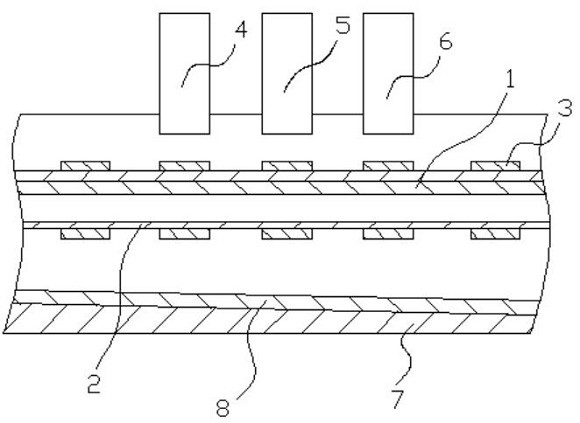
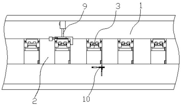
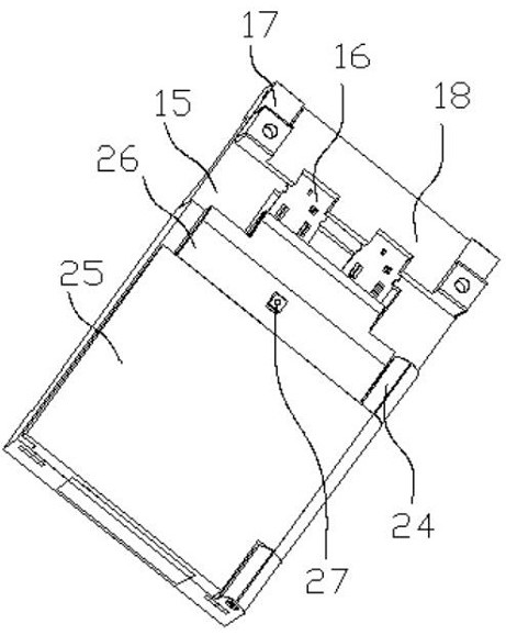
[0026] Such as Figure 1-6 As shown, the specific structure of the present invention is: a chip line post welding equipment that integrates blanking and collection, including a conveying trough 1, the middle part of the inner bottom plate of the conveying trough 1 is concave, and the concave part is equipped with a conveyor belt 2, the lower half of the conveyor belt 2 is located below the conveyor trough 1, and the outside of the conveyor belt 2 is evenly and fixedly connected with a carrier 3, and the carrier 3 includes a fixed connection on the conveyor belt 2. Upper carrier seat 15, described carr...


PUM


Abstract

The invention relates to chip wire column welding equipment integrating discharging and collecting. The chip wire column welding equipment comprises a conveying groove and carriers uniformly and fixedly connected to the outer side of a conveying belt. Each carrier comprises a carrier seat fixedly connected to the conveying belt, chip pressing block rotating seats are arranged on the carrier seats, rotatable chip pressing blocks are mounted on the chip pressing block rotating seats, and wire column supporting blocks and wire column pressing block rotating block seats are further arranged on the carrier seats. Wire column pressing rotating blocks are installed on the wire column pressing block rotating block seats, the wire column pressing rotating blocks are fixedly connected with wire column pressing blocks which are matched with the wire column supporting blocks and enable wire columns to be pressed, and a chip feeding device, a wire column feeding device and a spot welding device are arranged above the conveying groove. A chip pressing block rotating device and a wire column pressing block rotating device are arranged on an inner bottom plate of the conveying groove, a collecting groove is formed in the lower portion of the conveying groove, the inner bottom face of the collecting groove is an inclined face, an elastic sliding plate is laid on the inner bottom face of the collecting groove, and welding integrating discharging and collecting is achieved.

Description

technical field [0001] The invention relates to the field of assembly equipment, in particular to a chip line column welding equipment integrating blanking and collection. Background technique [0002] The welding combination of chips and wire posts is a common processing method for electronic product components. Generally, most of them are spot welded manually, and there are also some mechanized spot welding equipment. Chips 16 and wire posts 19 need to be placed first. into the corresponding carrier, and then perform compression and positioning, and then conduct spot welding through spot welding equipment. The structure is subjected to mechanized continuous processing, but it is still necessary to cooperate with manual installation and disassembly of the pressing and positioning structure, which is inefficient. Contents of the invention [0003] The purpose of the present invention is to provide a chip wire post welding equipment that integrates blanking and collection....

Claims


Application Information

Patent Timeline
Patent Type & Authority Applications(China)
IPC IPC(8): B23K37/00B23K37/04B23K101/36
CPCB23K37/00B23K37/0443B23K2101/36
Inventor 郑海林阮维民
Owner 长沙市鑫苑工业设计有限公司
Why Eureka
Try Eureka